Rockwell Automation Publication 1756-UM540E-EN-P - December 2017 115
Install ControlLogix Analog I/O Modules Chapter 6
Connect the Grounded End of the Cable
Before wiring the RTB, you must connect the ground wiring.
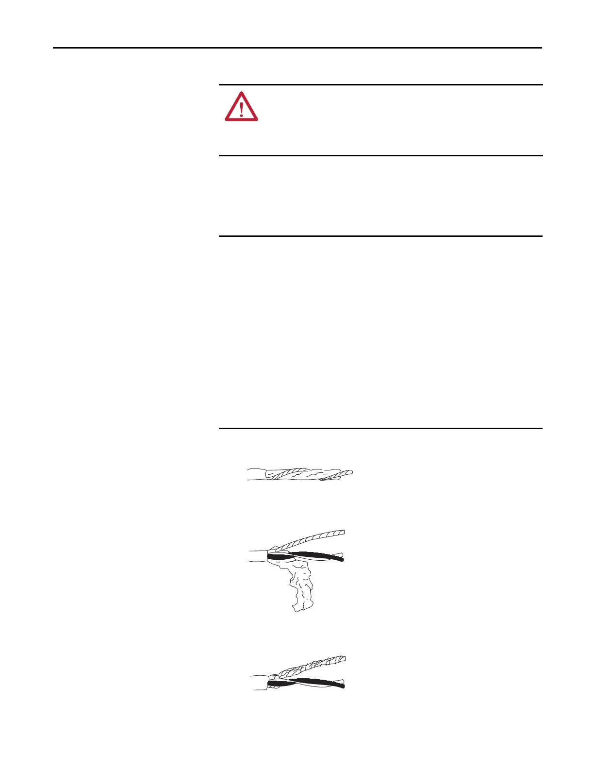
1. Remove a length of cable jacket from the Belden cable.
2. Pull the foil shield and bare drain wire from the insulated wire.
3. Twist the foil shield and drain wire together to form a single strand.
ATTENTION: The ControlLogix system has been agency certified using only the
ControlLogix RTBs (catalog numbers 1756-TBCH, 1756-TBNH, 1756-TBSH and
1756-TBS6H). Any application that requires agency certification of the
ControlLogix system using other wiring termination methods may require
application specific approval by the certifying agency.
We recommend that you ground the following ControlLogix analog module
shield and drain wires at the field-side:
• 1756-OF8I
• 1756-IRT8I
• 1756-IF8I on points that use the non-sourcing current/voltage
functionality
• 1756-IR12
• 1756-IT16
If you cannot ground the module shield and drain wires at field-side, ground
them at an earth ground on the chassis.
We recommend that you always ground the 1756-IF8I module at an earth
ground on the chassis when you use the module’s current sourcing
functionality.
 Loading...

