EasyManua.ls Logo

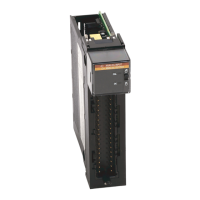
Allen-Bradley ControlLogix 1756-IF4FXOF2F User Manual

Allen-Bradley ControlLogix 1756-IF4FXOF2F
20 pages
To Next Page IconTo Next Page
Page #1 background imageLoading...
Page #1 background image
Publication 1756-IN004A-EN-P - February 2002
Installation Instructions
ControlLogix
High Speed Analog I/O Module
Catalog Number 1756-IF4FXOF2F
Obtain a User Manual
This product also has a user manual (pub. no. 1756-UM005). To view
it, visit www.ab.com/manuals
or www.theautomationbookstore.com.
To purchase a manual, you can:
contact your distributor or Rockwell Automation representative
visit www.theautomationbookstore.com
and place an order
call 800.963.9548 (USA/Canada) or 001.320.725.1574 (outside
USA/Canada)
To: See page:
Obtain a User Manual 1
Identify the Module Components 6
Prevent Electrostatic Discharge 5
Note the Power Requirements 7
Install the Module 7
Key the Removable Terminal Block/Interface Module 8
Wire the Module 11
Assemble the Removable Terminal Block and the Housing 13
Install the Removable Terminal Block onto the Module 13
Check the Indicators 14
Remove the Removable Terminal Block from the Module 15
Remove the Module 15
See 1756-IF4FXOF2F Specifications 16
Spare Allen-Bradley Parts
Question and Answer IconNeed help?

Do you have a question about the Allen-Bradley ControlLogix 1756-IF4FXOF2F and is the answer not in the manual?

Allen-Bradley ControlLogix 1756-IF4FXOF2F Specifications

General IconGeneral
CategoryI/O Systems
ManufacturerAllen-Bradley
Product TypeControlLogix
Series1756
Input Channels4
Output Channels2
Input TypeVoltage/Current
Output TypeVoltage/Current
Module TypeAnalog
Input Range±10V, 0-20mA, 4-20mA
Output Range±10V, 0-20mA, 4-20mA
Resolution16 bits
Operating Temperature0 to 60 °C

Summary

Important User Information

Environment and Enclosure

Safety and Handling Precautions

Prevent Electrostatic Discharge

Guidelines to prevent damage from static discharge when handling the module.

Removal and Insertion Under Power Warning

Warning regarding electrical arcs and explosion risk during module removal/insertion.

Identify the Module Components

Module Installation and Wiring

Note the Power Requirements

Details the power sources and current requirements for the module.

Install the Module

Step-by-step instructions for physically installing the module into the chassis.

Key the Removable Terminal Block/Interface Module

Explains how to use keying tabs and bands to prevent incorrect connections.

Wire the Removable Terminal Block

Instructions for wiring the RTB, including cable recommendations and grounding.

Connect Cable Ends

Detailed steps for preparing and connecting the grounded and ungrounded cable ends.

Wire the Module Diagrams

Wiring diagrams for current and voltage mode connections of the module.

Assemble and Install RTB

Steps to assemble the RTB housing and securely install it onto the module.

Check the Indicators

Module Removal Procedures

Remove the Removable Terminal Block

Steps to unlock and remove the RTB from the module.

Remove the Module

Instructions for safely pushing locking tabs and pulling the module from the chassis.

1756-IF4FXOF2F Specifications

General Module Specifications

Details general specifications like module location, backplane current, and power dissipation.

Environmental Conditions

Specifies operating, storage, humidity, and vibration conditions.

Input Specifications

Details input ranges, resolution, accuracy, and protection.

Output Specifications

Details output ranges, resolution, drive capability, and settling time.

Hazardous Locations Information

Information and warnings for operating the equipment in hazardous locations.

Related product manuals