ControlLogix High Speed Analog I/O Module 13
Publication
1756-IN004A-EN-P - February 2002
Assemble the Removable Terminal Block and the Housing
Install the Removable Terminal Block onto the Module
Before installing the RTB, make certain:
• field-side wiring of the RTB has been completed.
• the RTB housing is snapped into place on the RTB.
• the RTB housing door is closed.
• the locking tab at the top of the module is unlocked.
When you connect or disconnect the Removable
Terminal Block (RTB) with field side power applied, an
electrical arc can occur. This could cause an explosion in
hazardous location installations. Be sure that power is
removed or the area is nonhazardous before proceeding.
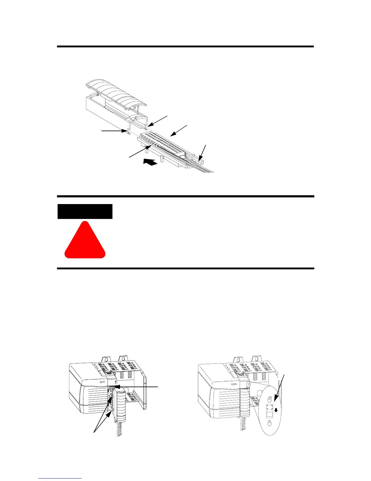
20858–M
Groove
Groove
Side edge of the RTB
Side edge of the RTB
Strain relief area
1. Align the grooves at the bottom of the housing with the side edges of the RTB.
2. Slide the RTB into the housing until it snaps into place.
20853–M 20854–M
Module
guide
RTB guides
Locking
tab
1. Align the side and top, bottom RTB guides with
the side, top and bottom module guides.
2. Press quickly and evenly to seat the RTB on the
module until the latches snap into place.
3. Slide the locking tab down to lock the RTB onto the module.
Spare Allen-Bradley Parts

 Loading...


