ControlLogix High Speed Analog I/O Module 11
Publication
1756-IN004A-EN-P - February 2002
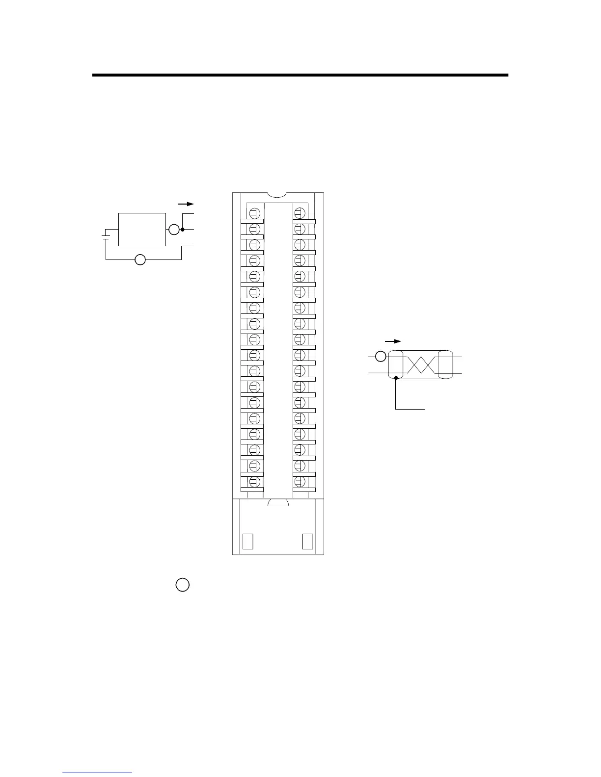
Wire the Module
You can only connect wiring to your module through an RTB or IFM.
The example below shows how to wire the module.
12
34
56
78
910
1112
1314
1516
1718
1920
2122
2324
2526
2728
2930
3132
3334
3536
+IN-1/V
IN-1/I
-IN-1
+IN-3/V
V OUT-1
IN-3/I
-IN-3
Not used
Not used
I OUT-1
RTN-1
Not used
+IN-0/V
IN-0/I
-IN-0
+IN-2/V
IN-2/I
-IN-2
1756-IF4FXOF2F Current Mode Wiring Diagram
2-Wire
Transmitter
A
A
A
(+) (-) i
i
42742
Shield
ground
Current
Output
Load
Not used
Not used
Not used
Not used
Not used
Not used
V OUT-0
Not used
Not used
I OUT-0
Not used
Not used
Not used
Not used
Not used
Not used
Not used
RTN-0
= Inline field device (i.e. strip chart recorder or meter)
A
Spare Allen-Bradley Parts

 Loading...


