10 ControlLogix High Speed Analog I/O Module
Publication
1756-IN004A-EN-P - February 2002
Connect ungrounded end of the cable
1. Prepare the non-grounded end of the cable.
2. Connect the insulated wires to:
• the RTB (as shown below) if the cable is grounded at the
field device.
or
• the field device if the cable is grounded at the chassis.
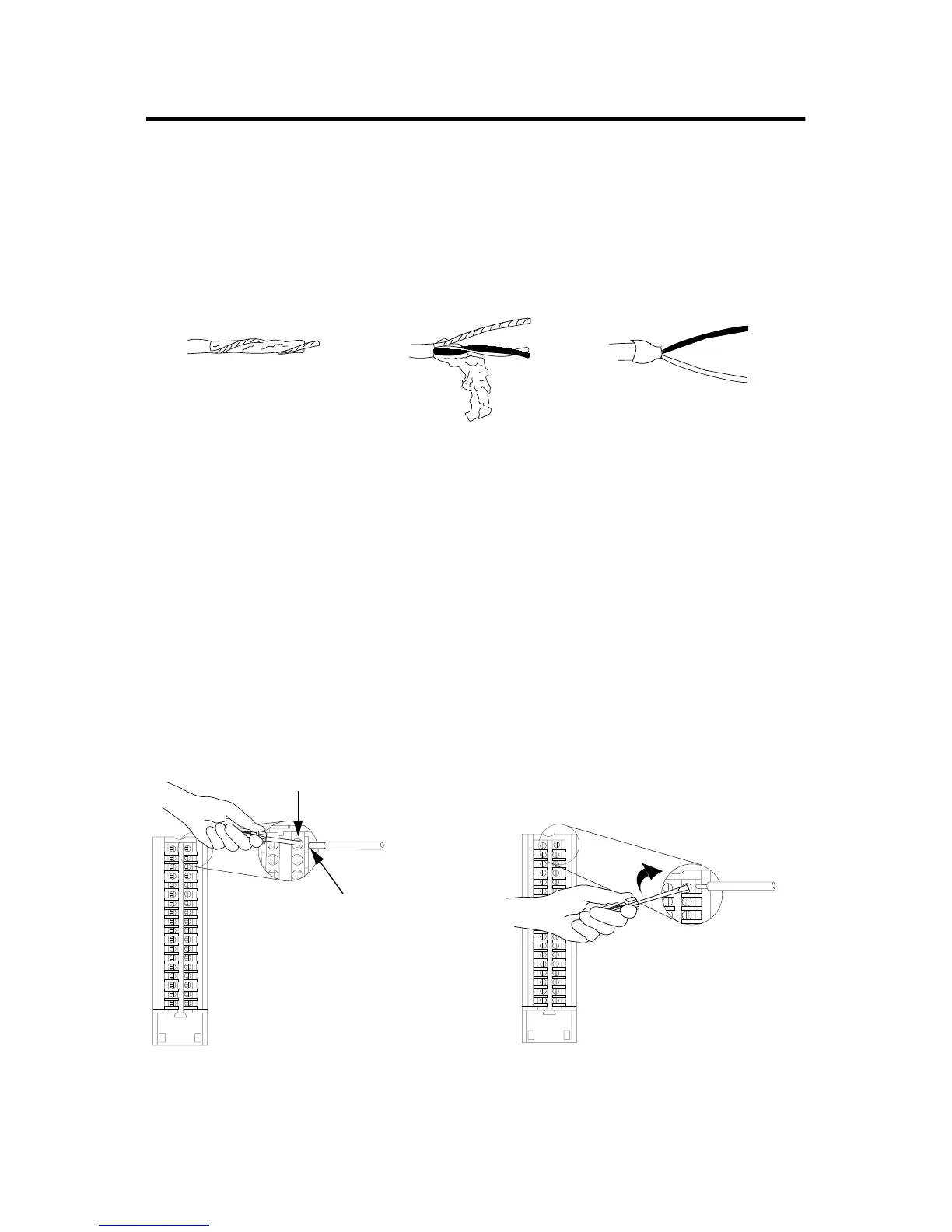
a. Remove a length
of cable jacket
from the
connecting cable.
b. Pull the foil shield
and bare drain
wire from the
insulated wire.
c. Cut the foil shield and drain
wire back to the cable
casing and apply shrink
wrap, exposing only the
insulated wires.
43182
Spring Clamp RTB Cage Clamp RTB
20860-M 20859-M
A. Strip 7/16 inch (11mm) maximum length
of wire.
B. Insert the screwdriver into the inner hole
of the RTB.
C. Insert the wire into the open
terminal and remove the
screwdriver.
A. Strip 3/8 inch (9.5mm) maximum length
of wire.
B. Insert the wire into the open terminal.
C. Turn the screw clockwise to close the
terminal on the wire.

 Loading...


