ControlLogix High Speed Analog I/O Module 9
Publication
1756-IN004A-EN-P - February 2002
Connect grounded end of the cable
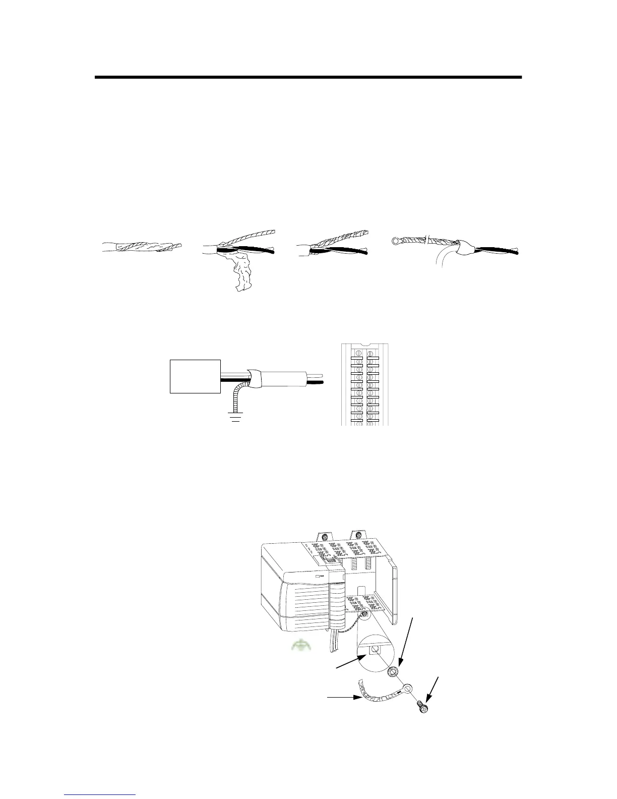
Ground one end of the cable only. Follow the steps below.
1. Prepare one end of the cable for grounding.
2. Ground the drain wire. We recommend grounding the drain
wire at the field device as shown below.
3. Connect the insulated wires to the field device.
If you cannot ground at the field device, follow these steps:
1. Prepare one end of the cable as shown in step 1.
2. Ground at an earth ground on the chassis as shown below.
3. Connect the insulated wires to the RTB.
a. Remove a length
of cable jacket
from the
connecting cable.
b. Pull the foil shield
and bare drain
wire from the
insulated wire.
c. Twist the foil shield
and drain wire
together to form a
single strand.
d. Attach a ground lug
and apply heat
shrink tubing to the
exit area.
20104-M
Field
Device
Drain wire
43183
20918-M
Connect the drain wire to a
chassis mounting tab.
Use any chassis mounting tab
that is designated as a
functional signal ground.
Chassis mounting tab
Drain wire with ground lug
4M or 5M (#10 or #12)
phillips screw and star
washer (or SEM screw)
4M or 5M (#10 or #12)
star washer
Spare Allen-Bradley Parts

 Loading...


