8 ControlLogix High Speed Analog I/O Module
Publication
1756-IN004A-EN-P - February 2002
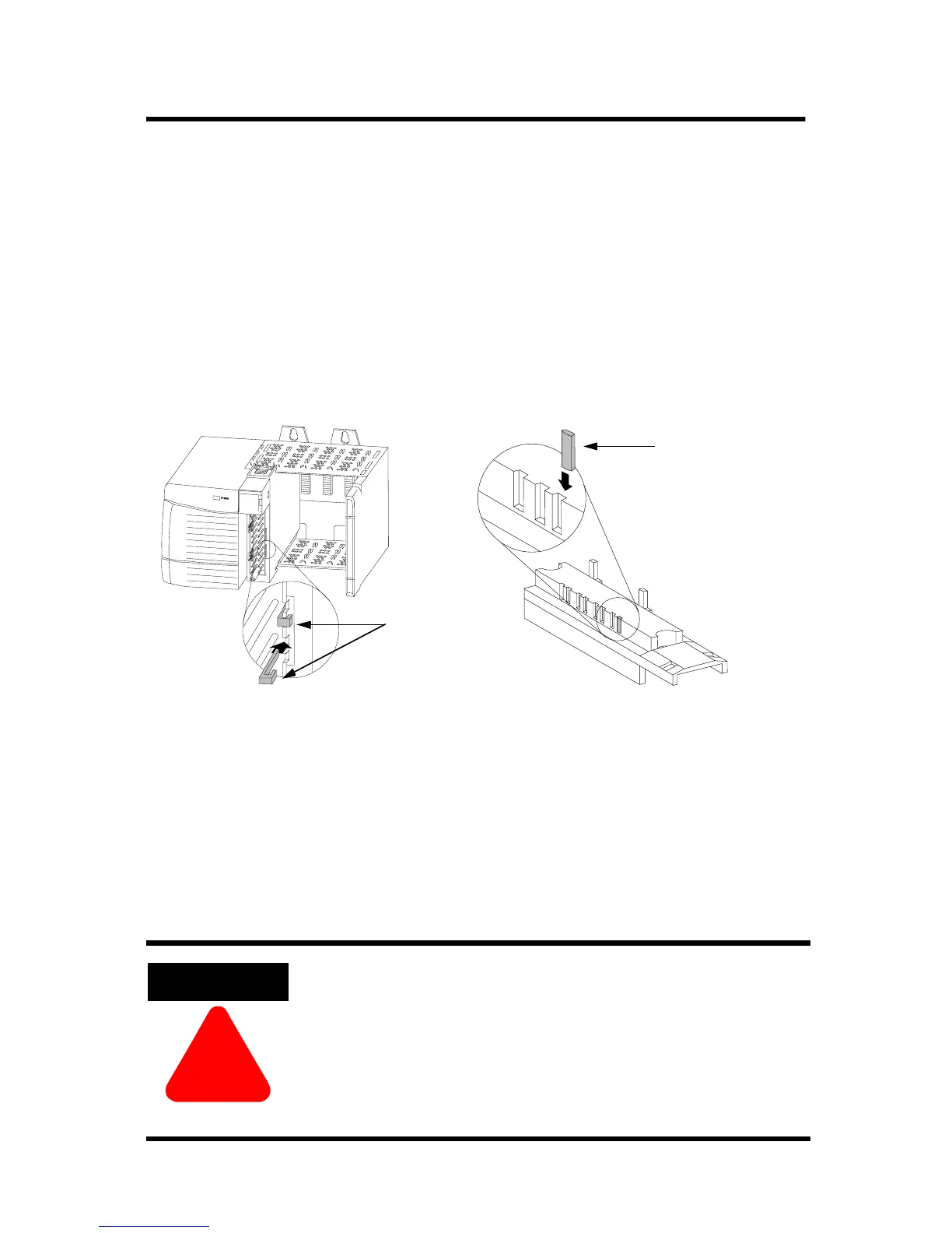
Key the Removable Terminal Block/Interface Module
Use the wedge-shaped keying tabs and U-shaped keying bands to
prevent connecting the wrong wires to your module.
Key positions on the module that correspond to unkeyed positions
on the RTB. For example, if you key the first position on the module,
leave the first position on the RTB unkeyed.
Reposition the tabs to rekey future module applications.
Wire the Removable Terminal Block
Wire the RTB with a 1/8 inch (3.2mm) maximum flat-bladed
screwdriver before installing it onto the module. Shielded cable is
required when using this module.
We recommend using Belden 8761 cable to wire the RTB. The RTB
terminations can accommodate 14-22 gauge shielded wire.
When you connect or disconnect the Removable
Terminal Block (RTB) with field side power
applied, an electrical arc can occur. This could
cause an explosion in hazardous location
installations. Make sure that power is removed or
the area is nonhazardous before proceeding.
20850–M
1. Insert the U-shaped band as shown.
2. Push the band until it snaps in place.
U-shaped
bands
1. Insert the wedge-shaped tab with rounded edge first.
2. Push the tab until it stops.
20851–M
Wedge-shaped tab
Key the Module Key the RTB/IFM

 Loading...


