12 Analog Output Module
Publication 1762-IN016D-EN-P - June 2013
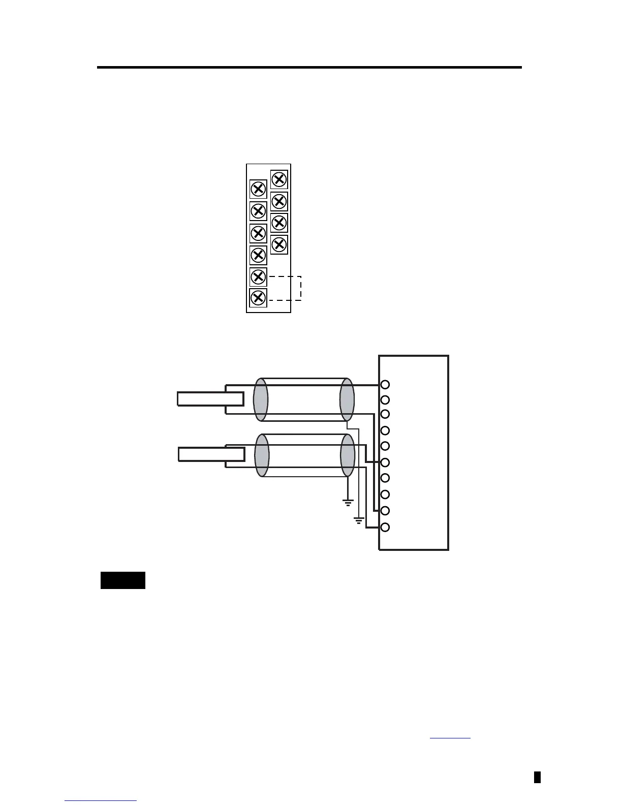
Output Wiring
Basic wiring of input devices to the 1762-OF4 is shown below.
Terminal Block Layout
Differential Sensor Transmitter Types
Ground the Module
This product is intended to be mounted to a well-grounded mounting surface such as a metal
panel. Additional grounding connections from the module’s mounting tabs or DIN rail (if used)
are not required unless the mounting surface cannot be grounded. Refer to Industrial
Automation Wiring and Grounding Guidelines, Allen-Bradley publication 1770-4.1
, for
additional information.
Grounding the cable shield at the module end only usually provides sufficient
noise immunity. However, for best cable shield performance, earth ground the
shield at both ends, using a 0.01 µF capacitor at one end to block AC power
ground currents, if necessary.
V out 3
V out 2
V out 1
V out 0
I out 3
I out 2
I out 1
I out 0
COM
COM
Commons connected
internally.
I out 0
I out 1
V out 2
V out 3
V out 0
V out 1
COM
I out 3
I out 2
COM

 Loading...


