Chapter 3
Addressing Modes for Your Remote I/O
3-17
When using double-slot block-transfer modules:
- The left slot of the two corresponding I/O groups must be
empty.
- You can place any single-slot I/O module in the right slot
of the two corresponding I/O groups.
When using single-slot block-transfer modules, the corresponding I/O
group must be empty.
The following rules apply when you assign I/O rack numbers:
When you select 1-slot addressing, set switches of switch assembly S1 to
assign the first I/O rack number of the chassis. The remote I/O adapter
module automatically assigns the next higher I/O rack number to the
remaining I/O groups of the chassis.
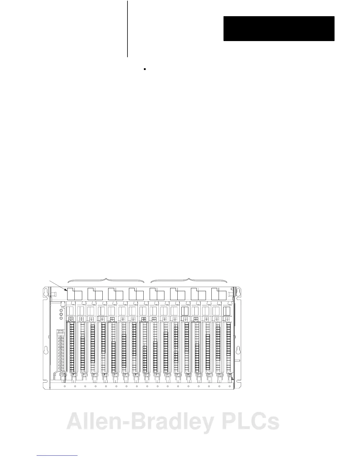
For example, if you want a 16-slot chassis that you set for 1-slot
addressing to begin with I/O rack number 0, set switches of switch
assembly S1 for I/O rack number 0. The adapter module automatically
assigns I/O rack number 1 to the remaining I/O groups of the chassis
(Figure 3.15).
Figure 3.15
Assigning
I/O Rack Numbers with 1slot Addressing
13077
Set switches of switch assembly S1
on the remote I/O adapter module
for I/O rack number 0. The adapter
automatically assigns I/O rack
number 1 to the remaining I/O group
of the chassis.
1771A4B I/O Chassis using 1slot addressing
I/O Group
Number
Assigned I/O Rack
Number 0
Assigned I/O Rack
Number 1
0 12 34 56 70 12 34 56 7
You assign one I/O rack number to eight I/O groups, regardless of which
addressing method you select.
Assigning
I/O Rack
Numbers with 1Slot
Addressing
Allen-Bradley PLCs
 Loading...


