Chapter 3
Addressing Modes for Your Remote I/O
3-19
Definition: The processor addresses one-half of an I/O module slot as one
I/O group.
Concept: The physical address of each I/O slot corresponds to two input
and two output image table words. The type of module you install (8-, 16-,
or 32-point) determines the number of bits in these words that are used.
You select 1/2-slot addressing by setting switches 5 and 6 of the I/O
chassis backplane switch assembly:
switch 5 to the OFF position
switch 6 to the ON position
With 1/2-slot addressing, since 32 inputs bits AND 32 output bits are
available in the processor’s image table for each I/O group, you can mix 8,
16 and 32-point I/O modules in any order in the I/O chassis.
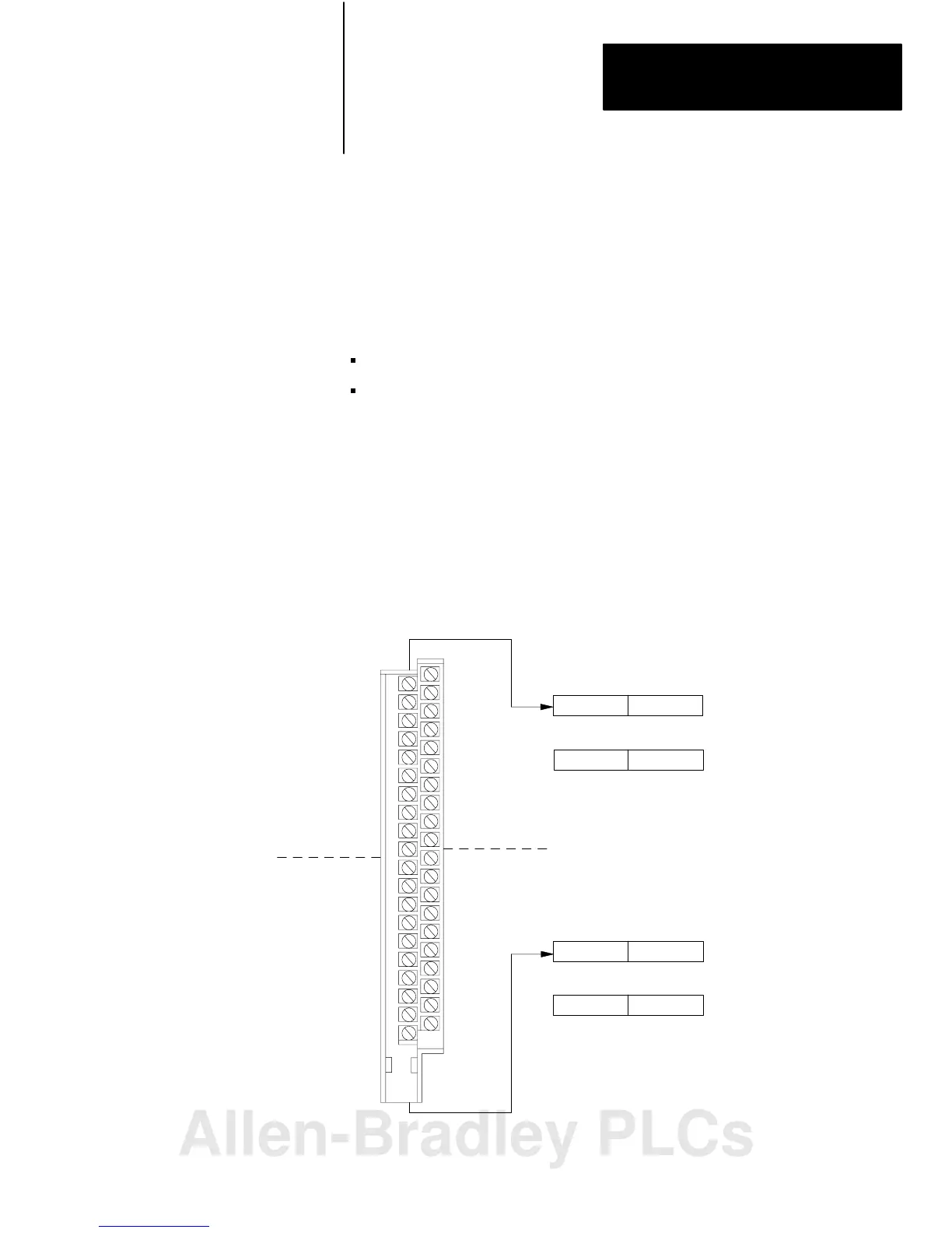
Figure 3.17 illustrates the 1/2-slot addressing concept with a 32-point I/O
module. A 32-point I/O module (with 1/2-slot I/O groups) uses two words
of the image table. When you use 8 and 16-point I/O modules with 1/2-slot
addressing, you get fewer total I/O points.
Figure 3.17
1/2slot
Addressing Concept
Input Word 0
Output Word 0
Image Table
Words Allocated
for I/O G roup 0
Input Word 1
Output Word 1
Image Table
Words Allocated
for I/O Group 1
14259
#
00
02
04
06
-
10
12
14
16
-
00
02
04
06
-
10
12
14
16
-
#
01
03
05
07
-
11
13
15
17
-
01
03
05
07
-
11
13
15
17
-
Unused
17 010 7
17 10 07
17 10 07
17 10
07
Unused
32-point Input Module
1/2-slot
I/O Group
0
1/2-slot
I/O G roup
0
1/2-slot
I/O Group
1
1/2-slot
I/O G roup
1
Input
Input
1/2 Slot Addressing
Allen-Bradley PLCs
 Loading...


