Chapter 3
Addressing Modes for Your Remote I/O
3-25
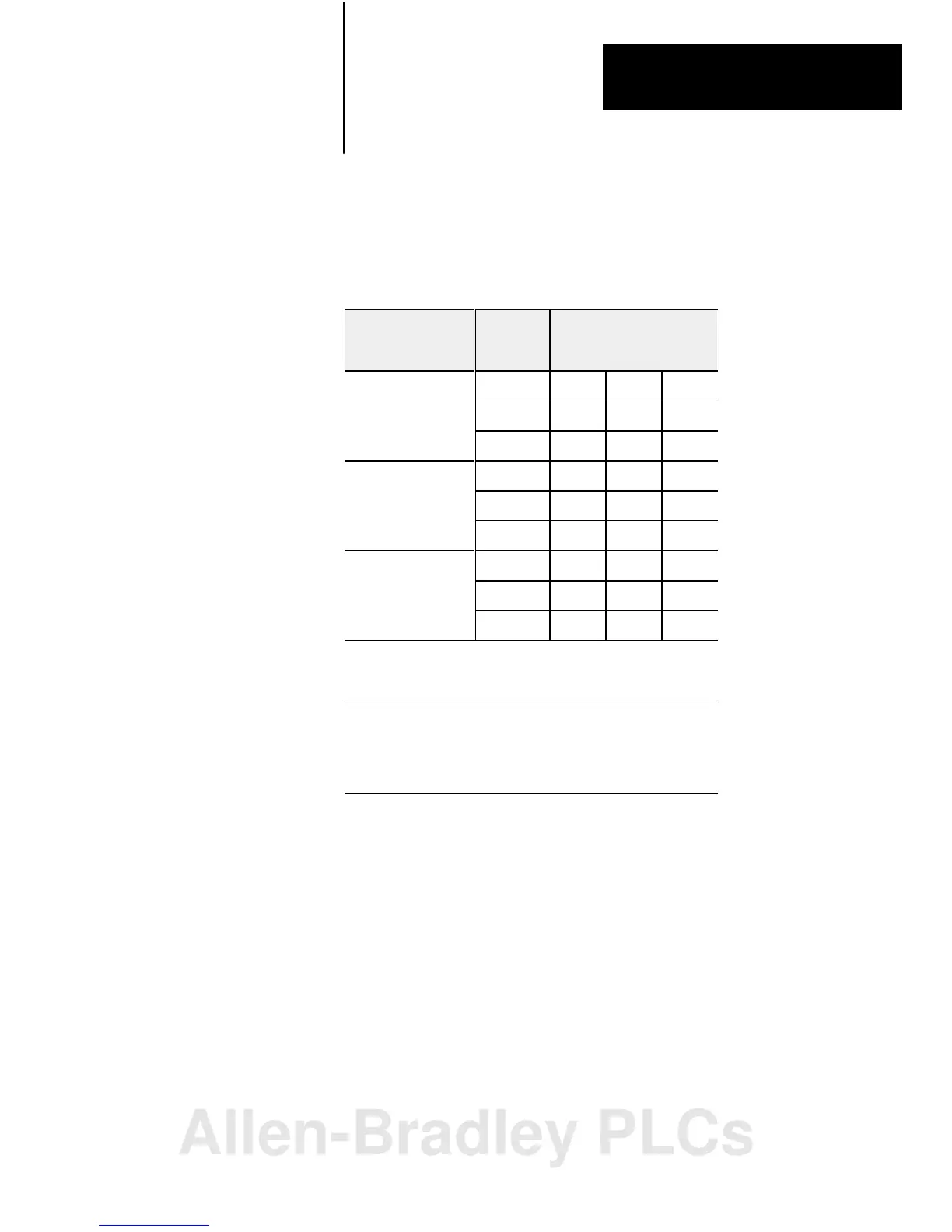
Table 3.C shows the addressing methods you can achieve with the Series B
chassis and the various remote I/O adapter modules.
Table 3.C
Series
B Chassis/Adapter Module Combinations
Remote I/O Adapter
Module Catalog
Number
I/O Points
Per
Module
Addressing Mode
2Slot 1Slot 1/2Slot
1771AS 8 Yes No No
16 * No No
32 No No No
1771ASB
8 Yes Yes No
eries A
16
* Yes No
32 No No No
1771ASB
8 Yes Yes Yes
eries B,
and D
16
* Yes Yes
32 No * Yes
* Conditional module placement: you must use an input module and
an output module in two adjacent slots of the I/O chassis beginning
with slot 0.
IMPORTANT: Series A I/O chassis let you use 2slot addressing with
8point I/O modules only, regardless of the type of adapter module you
use. This chart is valid for series B I/O chassis. You need series B I/O
chassis to achieve 1slot and 1/2slot addressing with 16point and
32point I/O modules.
In this chapter we discussed how to address your hardware and the various
remote I/O configurations and options you can use in your remote system.
I/O Chassis/Adapter Module
Combinations
Summary
Allen-Bradley PLCs
 Loading...


