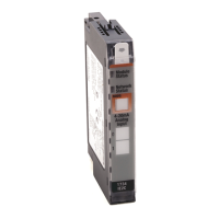
Specifications
A–2
Publication
1794-6.5.7 – March 1997
Specifications
1
– 1794-IT8 Thermocouple/mV Input Module
Thermal Dissipation Maximum 10.2 BTU/hr @ 31.2V dc
Keyswitch Position 3
General Specifications
External dc Power
Supply Voltage
Voltage Range
Supply Current
24V dc nominal
19.2 to 31.2V dc (includes 5% ac ripple)
19.2V dc for ambient temperatures less than 55
o
C
24V dc for ambient temperatures less than 55
o
C
31.2V dc for ambient temperatures less than 40
o
C
See derating curve.
150mA @ 24V dc
Cabling Thermocouples inputs
Millivolt inputs
Appropriate shielded thermocouple extension wire
3
Belden 8761
Dimensions Inches
(Millimeters)
1.8H x 3.7W x 2.1D
(45.7 x 94.0 x 53.3)
Environmental Conditions
Operational Temperature
Storage Temperature
Relative Humidity
Shock Operating
Non-operating
Vibration
0 to 55
o
C (32 to 131
o
F) See derating curve.
–40 to 85
o
C (–40 to 185
o
F)
5 to 95% noncondensing (operating)
5 to 80% noncondensing (nonoperating)
30 g peak acceleration, 11(+
1)ms pulse width
50 g peak acceleration, 11(+
1)ms pulse width
Tested 5 g @ 10–500Hz per IEC 68-2-6
Agency Certification
(when product or packaging is marked)
• CSA certified
• CSA Class I, Division 2
Groups A, B, C, D certified
• UL listed
• CE marked for all applicable directives
Installation Instructions Publication 1794-5.21
1
Specifications based on A/D filter first notch frequency of 10Hz
.
2
Use 1794-TB2 or -TB3 terminal base unit for millivolt inputs only
. Y
ou must use a 1794-TB3T terminal base unit when using
thermocouple inputs.
3
Refer to the thermocouple manufacturer for the correct extension wire.

 Loading...


