186 Rockwell Automation Publication 750-IN001P-EN-P - April 2017
Chapter 4 Power Wiring
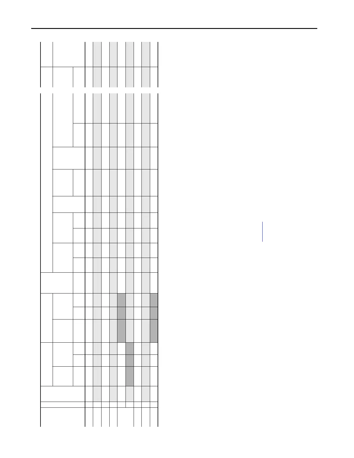
60 Hp 6 63 20x…E063 69.3 94.5 20x…E077 94.5 115.5 59.1 75 135 75 175 180 75 69.0 HSJ110
75 Hp 6
77 20x…E077 84.7 115.5 20x…E099 115.5 148.5 72.3 90 165 90 215 220 95 84.3 HSJ150
100 Hp 6 99 20x…E099 108.9 148.5 20x…E125 148.5 187.5 92.9 115 210 115 280 280 120 108.4 HSJ175
125 Hp 6
125 20x…E125 137.5 187.5 20x…E144 187.5 225.0 117.4 145 265 145 350 360 150 136.8 HSJ225
150 Hp 6 144 20x…E144 158.4 216.0
135.2 170 300 170 400 400 170 157.6 HSJ250
7
144 20x…E192 216.0 288.0 135.2 170 305 170 405 410 170 157.6 HSJ250
200 Hp 7 192 20x…E192 211.2 288.0 20x…E242 288.0 363.0 180.3 225 405 225 540 550 230 210.2 HSJ350
250 Hp 7
242 20x…E242 266.2 363.0 20x…E289 363.0 435.6 227.2 285 510 285 680 690 285 264.9 HSJ400
300 Hp 7 289 20x…E289 317.9 433.5
271.3 340 600 340 800 800 340 316.4 HSJ500
(1) “Applied Rating” refers to the motor that will be connected to the drive. For example, a “E063” drive can be used in Normal Duty mode on a 60 Hp motor, in Heavy-duty mode on a 50 Hp motor. The drive can be programmed for each mode. Wiring and fuses can be sized
based on the programmed mode. For any given drive catalog number, Normal Duty mode provides higher continuous current but smaller overload current when compared to Heavy-duty mode. See parameter 306 [Duty Rating]. See Specifications for an explanation of
Duty Ratings.
(2) Minimum protection device size is the lowest rated device that supplies maximum protection without nuisance tripping.
(3) Maximum protection device size is the highest rated device that supplies drive protection. For US NEC, minimum size is 125% of motor FLA. Ratings that are shown are maximum.
(4) Normal duty.
(5) Heavy duty.
(6) Circuit Breaker – inverse time breaker. For US NEC, minimum size is 125% of motor FLA. Ratings that are shown are maximum.
(7) When using a circuit breaker or time-delay fuse with a drive installed in a ventilated enclosure, the enclosure volume must be greater than or equal to the minimum volume specified in this column. Application-specific thermal considerations can require a larger
enclosure.
(8) Recommended Motor circuit protector – Instantaneous trip circuit breaker. Set the trip setting to the input current of the drive and size for the continuous current of the system.
(9) For Bulletin 140M with adjustable current range, set the current trip to the minimum range that the device will not trip.
(10) Manual Self-Protected (Type E) Combination Motor Controller, UL Listed for 480Y/277V and 600Y/347V AC Input. Not UL Listed for use on 480V or 600V Delta/Delta, corner ground, or high-resistance ground systems.
(11) Bulletin 140M must be frame C (C2E), frame D (D8E), or frame F (F8E).
(12) Bulletin 140M must be frame D (D8E) or frame F (F8E).
(13) When using a Manual Self-Protected (Type E) Combination Motor Controller, the drive must be installed in a ventilated or non-ventilated enclosure with the minimum volume that is specified in this column. Application-specific thermal considerations may require a
larger enclosure.
(14) See Fuse Certification and Test Data in PowerFlex AC Drives in Common Bus Configurations Application Guidelines, publication DRIVES-AT002
, for fuse self-certification and test data for Bussmann 170M and JKS fuses recommended for the DC bus fusing.
Table 23 - 600 Volt AC and 810 Volt DC Input Protection Devices – Wall Mount Frames 3…7 (Continued)
Applied
Rating
(1)
Frame
Cont.
Output
Amps
Drive Sized For Normal Duty Drive Sized For Heavy Duty Continuous
AC Input
AC Input Protection Devices Input
Quantities
DC Input
Protection
(14)
Catalog
Number
Output
Overload
Amps
Catalog
Number
Output
Overload Amps
Dual Element
Time Delay Fuse
Non-Time Delay
Fuse
Circuit
Breaker
Max
Size
(6)
Circuit Breaker,
Dual Element
Time Delay
Fuse
Motor
Circuit
Protector
(8)
140M Type E Combination Motor
Controller with Adjustable Current
Range
(9)
(10)
Continuous
DC Input
Non-Time
Delay Fuse
(x = F or G) 1 min 3 sec (x = F or G) 1 min 3 sec Amps Min
(2)
Max
(3)
Min
(2)
Max
(3)
Min Enclosure
Volume (in.
3
)
(7)
Cat. No. Min Enclosure
Volume (in.
3
)
(13)
Amps
 Loading...

