Rockwell Automation Publication 750-IN001P-EN-P - April 2017 203
Power Wiring Chapter 4
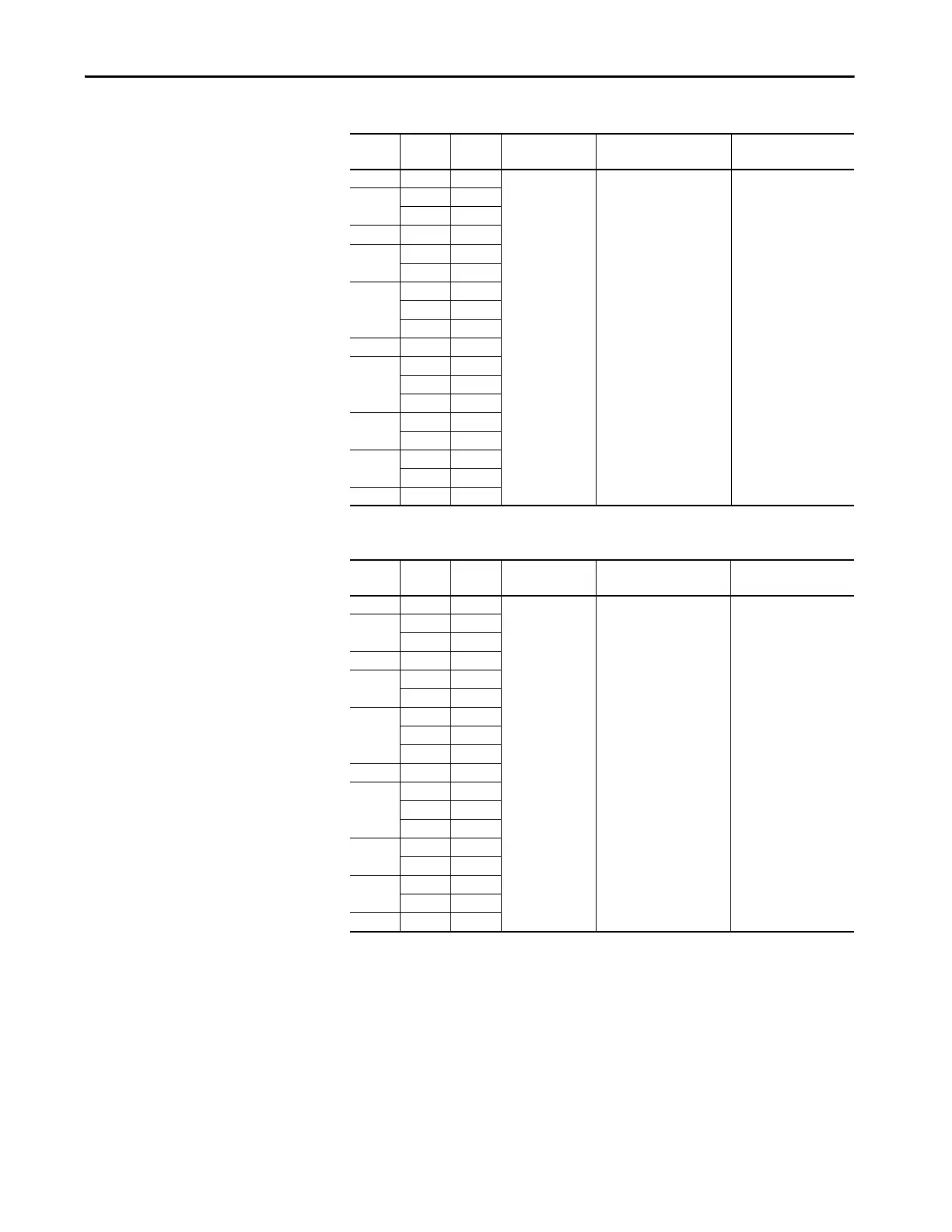
Table 37 - 690V, 60 Hz Input – Code P3 Thermal Magnetic Circuit Breaker Options
Table 38 - 690V, 60 Hz Input – Code P5 Molded Case Disconnect Switch Options (only floor
mount Frame 8)
kW Amps Duty Line Side Terminal
Lugs
Terminal Size Recommended Torque
N•m (lb•in)
200 215 Heavy
140G-M-TLA23 (2) 250…500 MCM kit of 3 31 (274)
250
265 Heavy
265 Normal
300 308 Heavy
315
330 Light
330 Normal
355
370 Heavy
370 Light
370 Normal
375 375 Heavy
400
410 Light
413 Heavy
415 Normal
450
460 Light
460 Normal
500
500 Light
500 Normal
530 530 Light
kW Amps Duty Line Side Terminal
Lugs
Terminal Size Recommended Torque
N•m (lb•in)
200 215 Heavy
140G-M-TLA23 (2) 250…500 MCM kit of 3 31 (274)
250
265 Heavy
265 Normal
300 308 Heavy
315
330 Light
330 Light
355
370 Heavy
370 Light
370 Normal
375 375 Heavy
400
410 Light
413 Heavy
415 Normal
450
460 Light
460 Normal
500
500 Light
500 Normal
530 530 Light
 Loading...

