EasyManuals Logo

Allen-Bradley 20A Installation Instructions

Allen-Bradley 20A
320 pages
To Next Page IconTo Next Page
To Previous Page IconTo Previous Page
Page #35 background imageLoading...
Page #35 background image
Rockwell Automation Publication 750-IN001P-EN-P - April 2017 35
Prepare for Installation Chapter 2
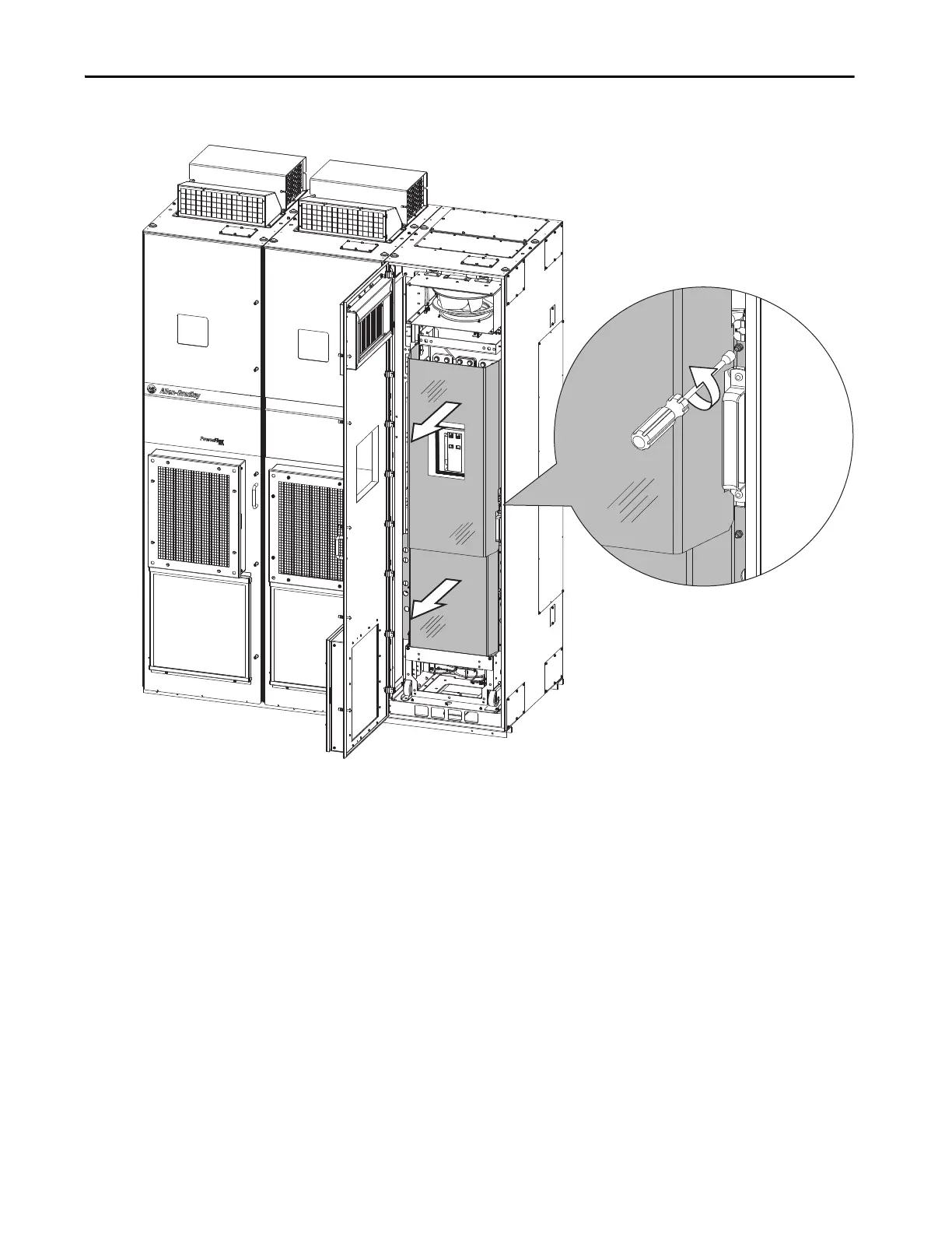
Figure 10 - Full Cabinet Options Bay Guard Floor Mount Frame 9
To remove the full bay guard, loosen the ten M5 screws. You do not need to
remove these screws.
To remove or replace the full bay guard, use this tool and torque:
Recommended torque = 2.8 N•m (25.0 lb•in)
Recommended driver = 8 mm Hexagonal socket

Table of Contents

Other manuals for Allen-Bradley 20A

Questions and Answers:

Question and Answer IconNeed help?

Do you have a question about the Allen-Bradley 20A and is the answer not in the manual?

Allen-Bradley 20A Specifications

General IconGeneral
BrandAllen-Bradley
Model20A
CategoryController
LanguageEnglish

Related product manuals