EasyManuals Logo

Allen-Bradley 20A Installation Instructions

Allen-Bradley 20A
320 pages
To Next Page IconTo Next Page
To Previous Page IconTo Previous Page
Page #70 background imageLoading...
Page #70 background image
70 Rockwell Automation Publication 750-IN001P-EN-P - April 2017
Chapter 3 Lift and Mount the Drive
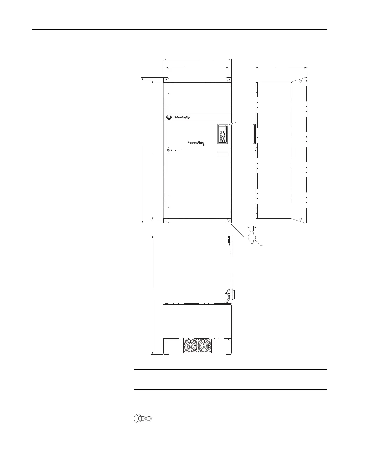
Figure 35 - IP54, NEMA/UL Type 12, Wall Mount Frame 6
Dimensions are in millimeters and (inches).
M10 (7/16 in.) mounting hardware recommended.
IMPORTANT Must use human interface module (HIM), catalog number 20-HIM-C6S, to
meet enclosure rating.
558.8
(22.00)
609.4
(23.99)
464.7
(18.30)
1298.3
(51.11)
1238.3
(48.75)
1058.1
(41.66)
10.5 (0.41)
ø22.0 (0.87)
HIM

Table of Contents

Other manuals for Allen-Bradley 20A

Questions and Answers:

Question and Answer IconNeed help?

Do you have a question about the Allen-Bradley 20A and is the answer not in the manual?

Allen-Bradley 20A Specifications

General IconGeneral
BrandAllen-Bradley
Model20A
CategoryController
LanguageEnglish

Related product manuals