EasyManuals Logo

Allen-Bradley 20A Installation Instructions

Allen-Bradley 20A
320 pages
To Next Page IconTo Next Page
To Previous Page IconTo Previous Page
Page #75 background imageLoading...
Page #75 background image
Rockwell Automation Publication 750-IN001P-EN-P - April 2017 75
Lift and Mount the Drive Chapter 3
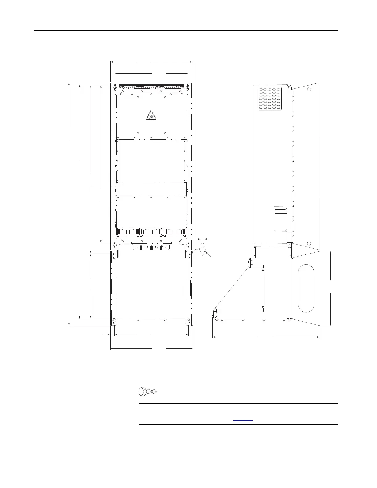
Figure 40 - NEMA/UL Type 1, Wall Mount Frame 7
Dimensions are in millimeters and (inches).
M8 (5/16 in.) mounting hardware recommended.
430.0
(16.93)
1271.0
(50.04)
1221.0
(48.07)
881.8
(34.72)
825.0
(32.48)
380.0
(14.96)
389.0
(15.31)
20.5
(0.81)
561.0
(22.08)
389.2
(15.32)
8.5 (0.33)
ø16.0 (0.63)
430.0
(16.93)
339.2
(13.35)
IMPORTANT NEMA Type 1 kit (catalog number 20-750-NEMA1-F7) does change the
mounting dimensions in Figure 34
.

Table of Contents

Other manuals for Allen-Bradley 20A

Questions and Answers:

Question and Answer IconNeed help?

Do you have a question about the Allen-Bradley 20A and is the answer not in the manual?

Allen-Bradley 20A Specifications

General IconGeneral
BrandAllen-Bradley
Model20A
CategoryController
LanguageEnglish

Related product manuals