48 Rockwell Automation Publication 1756-RM100F-EN-P - October 2018
Chapter 3 Replacement Considerations with CompactLogix and Compact GuardLogix Systems
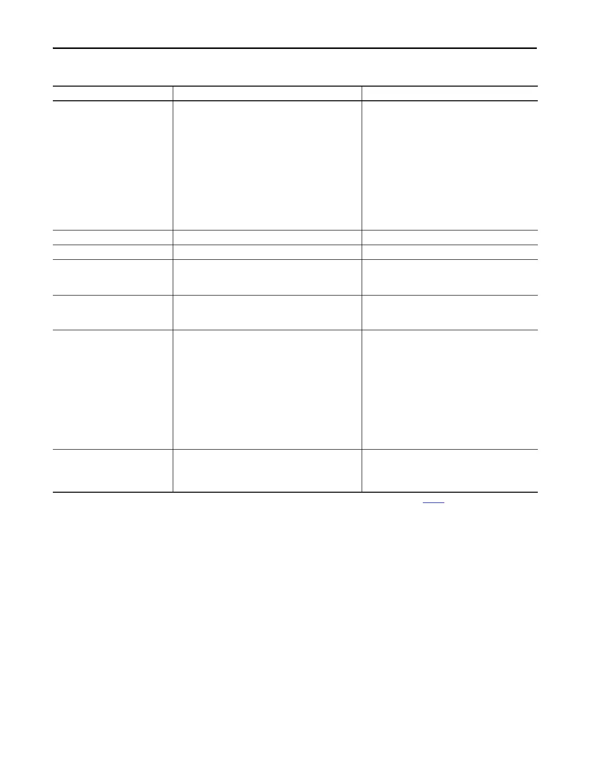
Voltage and current ratings Controller power: 500 mA @ 5.1V DC and 225 mA @ 24V DC MOD Power: 450 mA @ 18…32V DC
MOD Power Inrush: 850 mA for 125 ms
SA Power: 10 mA @ 0…32V DC
25 mA @ 0…240V AC,
47…63 Hz
ATEX/IECEX, 125V AC Max
MOD Power (Passthrough)
(3)
: 9.55 A @ 18…32V DC
SA Power (Passthrough)
(4)
: 9.95 A @ 0…32V DC
9.975 A @ 0...240V AC,
47...63 Hz
ATEX/IECEX, 125V AC Max
Energy storage module Non-removable Non-removable
Weight, approx 0.31 kg (0.68 lb) 0.394 kg (.868 lb)
Wire category
(1)
3 - on USB port
2 - on Ethernet port
3 - on USB port
1 - on power ports
2 - on Ethernet port
Wire size RJ45 connector according to IEC 60603-7, 2 or 4 pair Category 5e
minimum cable according to TIA 568-B.1 or Category 5 cable
according to ISO/IEC 24702
Ethernet connections:
Ethernet Cabling and Installation according to IEC 61918 and
IEC 61784-5-2
Removable terminal block Not Applicable Kit 5069-RTB64-SCREW or kit 5069-RTB64-SPRING
You must order the kit separately. RTBs do not ship with the
controller.
5069-RTB4-SCREW, 5069-RTB6-SCREW connections:
0.5...1.5 mm
2
(22…16 AWG) solid or stranded copper wire
rated at 105 °C (221 °F), or greater, 3.5 mm (0.14 in.) max
diameter including insulation, single wire connection only
5069-RTB4-SPRING, 5069-RTB6-SPRING connections:
0.5...1.5 mm
2
(22…16 AWG) solid or stranded copper wire
rated at 105 °C (221 °F), or greater, 2.9 mm (0.11 in.) max
diameter including insulation, single wire connection only
Reset Button Clears the user application and memory but retains the firmware
revision and all network settings
A stage 1 reset clears the user application program and
memory, but retains the controller IP address.
A stage 2 reset returns the controller to out-of box settings
(including firmware), and clears all network settings.
(1) Use this conductor category information for planning conductor routing. See the Industrial Automation Wiring and Grounding Guidelines, publication 1770-4.1.
(2) Data size = 32-bits / 1-DINT
(3) Maximum level of MOD Power current that the module can pass through to the next module in the system. The specific level of current passed through varies based on system configuration.
(4) Maximum level of SA Power current that the module can pass through to the next module in the system. The specific level of current passed through varies based on system configuration.
Table 8 - Technical Specifications
Attribute CompactLogix 5370 L3 Controller CompactLogix 5380 Controller
 Loading...


