Do you have a question about the Allen-Bradley GuardLogix 5580 and is the answer not in the manual?
Provides SIL certifications and Performance Level for controllers.
Discusses requirements for performing proof tests of equipment used in safety systems.
Provides examples of SIL 3 and SIL 2 systems and how devices connect.
Lists product specifications and agency certifications for controllers.
Defines system reaction time as the worst-case time from event to safe state.
Explains the safety task period and the maximum permissible time for processing.
Provides contact details for reporting device failures to Rockwell Automation.
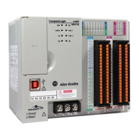
Describes the GuardLogix 5580 controller, its primary controller, and safety partner.
Details the SIL 2 capable Compact GuardLogix 5380 controller and its components.
Provides examples of network communication configurations, including EtherNet/IP.
Explains how DeviceNet bridges enable communication with Safety I/O modules.
Guides on using Studio 5000 Logix Designer for programming GuardLogix safety controllers.
Explains how Safety I/O devices are treated as safe states.
Defines input and output reaction times and their calculation.
Covers commissioning, ownership, and configuration of Safety I/O devices.
Explains the safety I/O configuration signature and its verification.
Details procedures for replacing safety I/O devices and their configuration.
Explains the concept of a Unique Node Reference (UNID) in CIP Safety protocol.
Describes how Safety Network Numbers (SNN) are assigned to subnets.
Illustrates the extent of a routable CIP Safety system.
Provides guidelines on automatically generating and manually assigning SNN values.
Explains how Safety Network Numbers are assigned to safety devices.
Details the two formats for SNNs: Time-based and Manual.
Explains how SNNs are set for out-of-box CIP Safety I/O devices.
Explains the distinction between standard and safety components in GuardLogix systems.
Details the characteristics and limitations of the safety task in GuardLogix controllers.
Compares requirements for SIL 2 and SIL 3 safety applications.
Discusses differences in I/O modules for safety integrity levels.
Provides precautions and guidelines for using HMIs in SIL-rated GuardLogix systems.
Covers reading and changing parameters in safety-related systems via HMIs.
Defines safety programs and their attributes, including scheduling and scope.
Describes safety routines, their limitations, and usage within safety programs.
Explains safety tags, their attributes, and composition.
Details mapping standard tags into safety tags for synchronization.
Outlines requirements for creating, operating, and maintaining safety applications.
Recommends practices for developing and testing safety applications.
Illustrates the steps required for commissioning a GuardLogix safety system.
Guides on creating a safety function specification for verification.
Details requirements for creating application logic and instructions.
Describes the process of testing the application program.
Explains how to generate a safety signature for controller operation.
Guides on checking the application program against the specification.
Outlines steps to confirm the downloaded, tested, and retained safety program.
Discusses the requirement for independent third-party review of safety systems.
Recommends safety-locking the controller to protect safety components.
Details requirements for downloading the safety application program.
Explains how to upload the safety signature and tag values from the controller.
Covers firmware updates and program storage using a memory card.
Explains how to force data for safety-unlocked projects without signatures.
Details how to inhibit specific safety I/O devices or producer controllers.
Covers guidelines for performing online edits on safety logic.
Outlines rules for changing safety application programs in Studio 5000.
Details the process and impact of performing online edits on safety programs.
Explains the need to plan and analyze modifications for impact on safety systems.
Explains the use of status indicators for general diagnostics.
Guides on viewing safety tag connection status and device operating status.
Describes how CIP Safety protocol allows data recipients to determine data status.
Explains the de-energize to trip system where zero is the safe state.
Details using GSV/SSV instructions to get/set controller system data.
Categorizes faults in GuardLogix and Compact GuardLogix systems.
Explains how to view faults using the Controller Properties dialog box.
Shows fault codes specific to GuardLogix and Compact GuardLogix controllers.
Describes the OK status indicator and faults related to the safety partner.
Lists safety application instructions certified for SIL 2 or SIL 3 applications.
Guides on creating a unique test project for creating and testing Add-On Instructions.
Provides guidance on creating Add-On Instructions using Logix5000 Controllers manual.
Explains the instruction signature for determining if an instruction has been modified.
Defines the safety instruction signature as an ID identifying execution characteristics.
Details performing tests for SIL 2 or SIL 3 Add-On Instructions.
Discusses third-party review requirements for safety Add-On Instructions.
Explains how to create a signature history entry for future reference.
Provides guidelines for exporting and importing safety Add-On Instructions.
Explains comparing signatures to ensure the validity of imported Add-On Instructions.
Describes the process of getting an application to run properly.
Guides on performing engineering tests of the application and safety system.
Discusses third-party review requirements for safety system approval.
Defines the maximum age of safety packets on a connection before a fault occurs.
Explains how RPI specifies the period for data updates over a connection.
Describes how to view and reset the Maximum Observed Network Delay.
Defines system reaction time and its components.
Explains how to calculate Logix system reaction time for various chains.
Describes Logix system reaction time for a simple input to logic to output chain.
Explains Logix system reaction time for chains using produced/consumed safety tags.
Identifies factors influencing Logix Reaction Time components.
Guides on configuring input module delay time in Studio 5000 Logix Designer.
Details how to configure input/output safety connection reaction time limits.
Explains how to select safety task period, priority, and watchdog time.
Provides steps to view or configure safety-tag connection data.
A checklist for planning, programming, and starting a GuardLogix safety application.
An individual checklist for every safety input in the system.
An individual checklist for every safety output in the system.
A checklist to help maintain safety when creating or modifying a safety application.
States the useful life of GuardLogix controllers is 20 years.
Provides safety data, including PFD and PFH values for safety I/O modules.
Presents safety parameters and calculations related to product failure rates.
Explains how safety input values are set to safe state upon CIP Safety connection fault.
Provides examples of application logic to latch and reset I/O failures.
| Series | GuardLogix 5580 |
|---|---|
| I/O Capacity | Up to 256 I/O modules |
| Programming Environment | Studio 5000 Logix Designer |
| Safety Integrity Level | SIL 3 |
| Performance Level | PL e |
| Controller Type | Safety Programmable Logic Controller (PLC) |
| Processor | Dual-core |
| I/O Support | Digital, Analog, Safety I/O |
| Communication Protocols | EtherNet/IP, ControlNet, DeviceNet |
| Operating Temperature | 0°C to 60°C (32°F to 140°F) |
| Certifications | UL, CE |