Rockwell Automation Publication 1756-RM012B-EN-P - April 2018 11
Safety Integrity Level (SIL) Concept Chapter 1
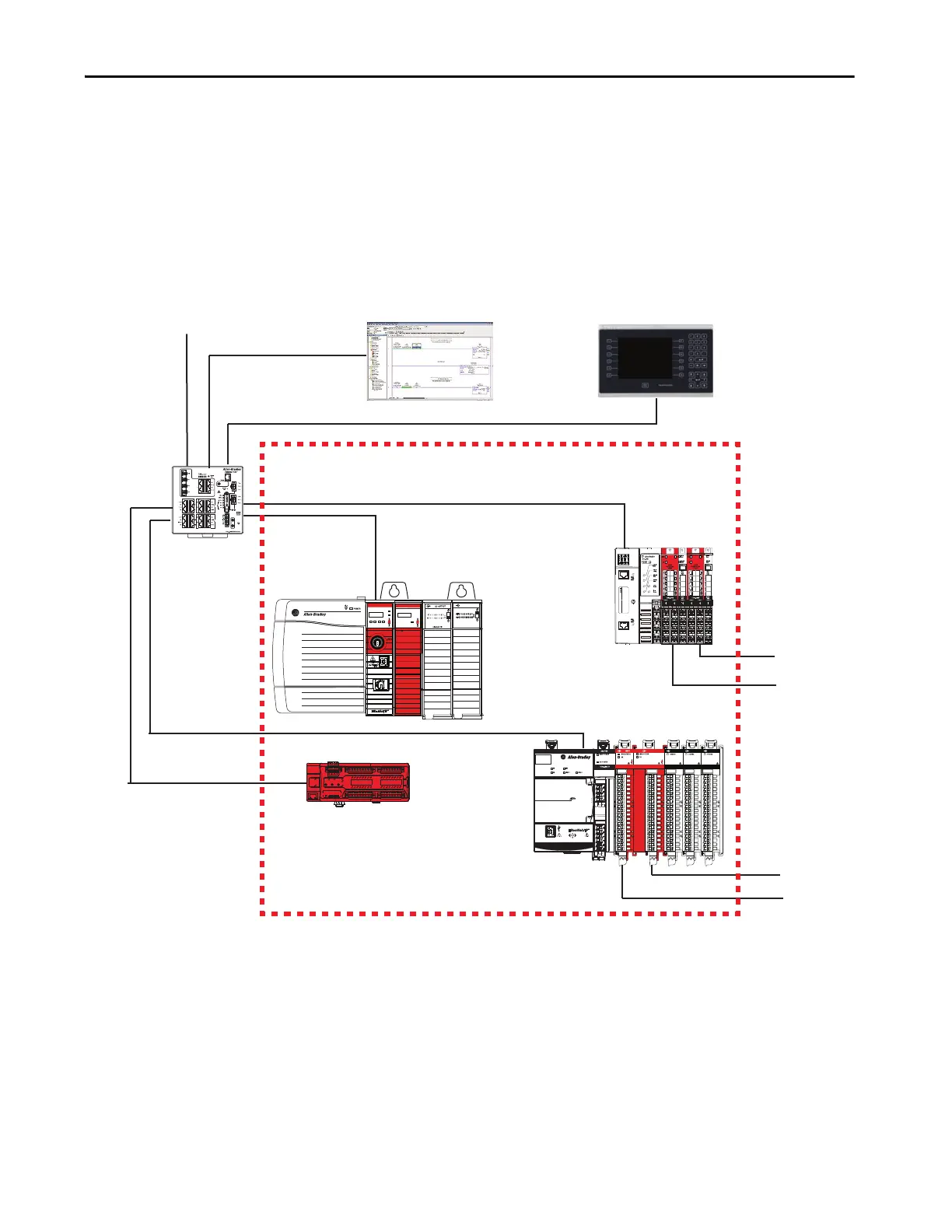
GuardLogix Architecture
This section provides examples of SIL 3 and SIL 2 systems, including:
• The overall safety function
• The GuardLogix portion of the overall safety function
• How other devices (for example, HMI) are connected, while operating
outside the function
Figure 1 - Example SIL 3 System
-
OK
Logix55L8SP™
NET
LINK
RUN
REM
RUN
PROG
FORCE SD OK
Logix5584ES™
DC INPUT
5069-OBV8S
COUNTER
5069-HSC2xOB4
DC INPUT
5069-IB16
DC OUTPUT
5069-OB16
5069-IB8S
OUTPUT
Compact 5000™ I/O
SA Power MOD Power
Sensor
Actuator
HMI Display
Stratix® 5400 Switch
Programming Software
To Plant-wide Ethernet Network
Actuator
Sensor
Safety I/O Module on
Ethernet Network
Safety System
GuardLogix 5580 Controller
5069-AEN2TR
Compact 5000 I/O Modules
Compact 5000 I/O Safety Modules
Safety I/O Module on
Ethernet Network

 Loading...


