Do you have a question about the Allen-Bradley Compact GuardLogix 5370 and is the answer not in the manual?
Details on WARNING, ATTENTION, IMPORTANT labels and hazard types.
Definitions of abbreviations and terms used throughout the manual.
Lists related Rockwell Automation publications for further information.
Key requirements for SIL 3/PLe certification and safety network number.
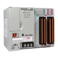
Describes components used in a typical controller system setup.
Identifies required software and versions for programming.
Essential environmental and installation precautions for safe operation.
Step-by-step guide for installing the SD card into the controller.
Key considerations for planning the controller system layout.
Guidelines on mounting the controller system on a panel or DIN rail.
Information on how to connect power to the controller system.
Instructions for connecting the controller to an EtherNet/IP network.
Explains how to assign a unique IP address to the controller.
Steps for downloading current firmware to the controller.
How to set the controller's operating mode (RUN, REM, PROG).
Steps to create and manage a new controller project in Logix Designer.
How to set and manage passwords for safety-locking the controller.
Reduces errors by matching project device definitions to installed devices.
Configures the controller as the Coordinated System Time (CST) master.
Explains the CIP Safety protocol and Safety Network Number (SNN).
Details on assigning and managing unique Safety Network Numbers.
Overview of EtherNet/IP services, software, and functionality.
Explains DLR, Linear, and Star network topology support.
Overview of DeviceNet communication via the 1769-SDN scanner.
Options for selecting standard I/O modules (Local, Distributed).
Points to consider when validating I/O layout placement.
Defines the frequency for data transfer between controller and I/O modules.
How to calculate power consumption for system banks.
Steps to add and configure a Compact I/O module.
Ways to monitor standard I/O module status and faults.
Defines configuration requirements when adding safety I/O devices.
Steps to add and configure safety I/O devices in the controller project.
Explains how to set the Safety Network Number for safety devices.
Sets the maximum age of safety packets for connection fault detection.
Procedures for replacing safety I/O devices on an Ethernet network.
Explains how tasks schedule and prioritize program execution.
Describes how programs group data and logic for execution.
Explains using tags (alphanumeric names) to address data variables.
Specifies the percentage of time devoted to service communication.
Describes the automatically created safety task for safety projects.
Attributes of safety programs and their components.
How to create and assign properties to safety tags.
How to use produced/consumed tags for sharing safety data between controllers.
Methods to protect the application from unauthorized changes.
Creates a signature to identify and protect the safety project integrity.
Lists supported axes types for integrated motion applications.
Enables time synchronization (CIP Sync) for integrated motion.
Steps to add and configure drives for integrated motion on EtherNet/IP.
Factors affecting going online, including project match and safety status.
Steps to transfer the project from computer to controller.
Steps to transfer the project from controller to computer.
Steps to connect to the controller to monitor its execution.
How to view controller status, forces, edits, and safety status.
How to monitor the status of standard and safety connections.
Classification of faults: nonrecoverable controller, safety, or recoverable.
Table of fault codes specific to Compact GuardLogix controllers.
Retrieving and setting controller data using GSV/SSV instructions.
Explains the use of SD cards for nonvolatile memory storage.
Steps to save a safety project and controller firmware to the SD card.
How to initiate a load from nonvolatile memory into controller memory.
Using Firmware Supervisor to manage firmware updates.
Explains the RUN status indicator on the controller.
Explains the I/O state indicator for device communication.
Explains the NS status indicator for Ethernet network status.
Indicates safety task and output status.
Indicates whether the safety task is locked or unlocked.
Steps and implications of changing a project from standard to safety controller.
Steps and implications of changing a project from safety to standard controller.
Lists topics with new or updated information in the manual.
| Brand | Allen-Bradley |
|---|---|
| Model | Compact GuardLogix 5370 |
| Category | Controller |
| Language | English |