Rockwell Automation Publication 1769-UM022C-EN-P - June 2018 27
Install the Controller Chapter 2
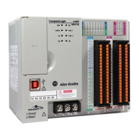
4. Use the upper and lower tongue-and-groove slots to secure the
controller and power supply together.
5. Move the power supply back along the tongue-and-groove slots until the
bus connectors align with each other.
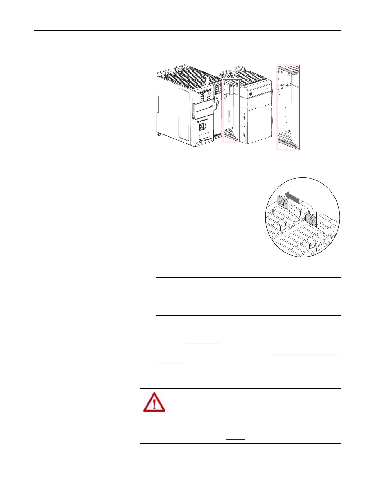
6. Use your fingers or a small screwdriver to
push the bus lever of the power supply
back slightly to clear the positioning tab.
7. Move the bus lever of the power supply
to the left of the positioning tab until it
clicks; make sure that it locks.
8. If your system does not use any local
expansion modules, use the
tongue-and-groove slots described
earlier to attach a 1769-ECR Compact
I/O end cap terminator to the last module in the system.
9. Wire the 1769 Compact I/O power supply according to the directions
in the Compact I/O Expansion Power Supplies installation instructions,
publication 1769-IN028
.
If you are using local expansion modules, see Local Expansion Modules
on page 83.
Mount the System
IMPORTANT You must install an end cap onto the right side of the Compact
GuardLogix 5370 controller system either at the end of the
controller or at the end of any local expansion modules that can be
installed onto the controller.
Upper
Tong ue -a nd-groo ve
Slot
Lower
Tong ue -a nd-groo ve
Slot
ATTENTION: This controller must be mounted to a well-grounded mounting
surface, such as a metal panel. Additional grounding connections from the
power supply’s mounting tabs or DIN rail (if used) are not required unless the
mounting surface cannot be grounded.
See Industrial Automation Wiring and Grounding Guidelines, Rockwell
Automation publication 1770-4.1
, for additional information.
 Loading...


