28 Rockwell Automation Publication 1769-UM022C-EN-P - June 2018
Chapter 2 Install the Controller
You can mount a Compact GuardLogix 5370 controller system on a panel or
on a DIN rail.
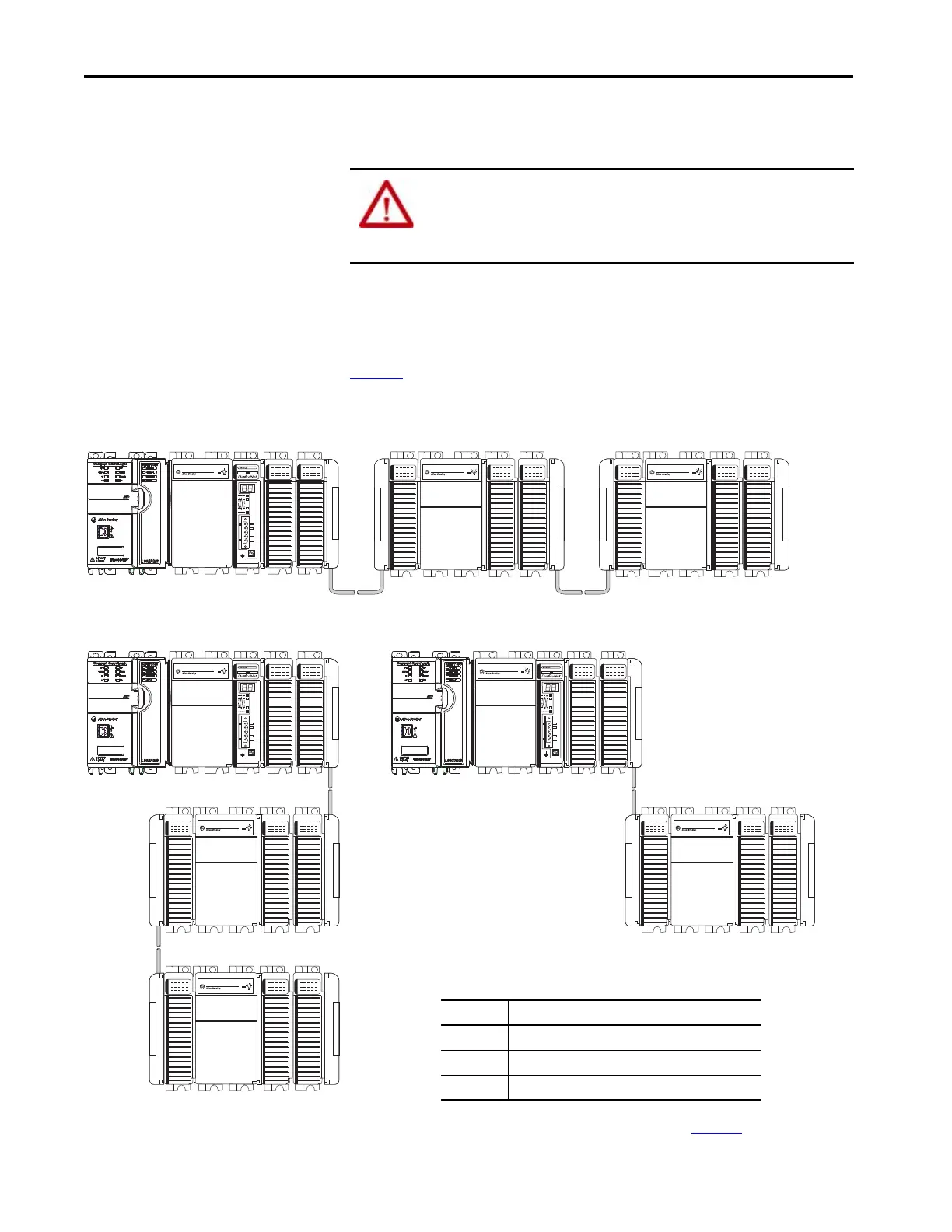
A Compact GuardLogix 5370 controller system must be mounted so that the
modules are horizontal to each other. If you separate modules into multiple
banks, the banks can be vertical or horizontal to each other.
Figure 2
shows system examples with local expansion modules included.
Figure 2 - Example of Banks and System Configurations
ATTENTION: During panel or DIN rail mounting of all devices, be sure that
all debris (such as metal chips or wire strands) is kept from falling into the
controller. Debris that falls into the controller can cause damage while the
controller is energized.
1769-CRLx Cable
Horizontal Orientation
Bank 1 Bank 2
Bank 3
1769-CRLx Cable
Vertical Orientations
Bank 1
Bank 2
1769-CRRx Cable
1769-ECR
End Cap
1769-ECR
End Cap
Bank 3
769-CLLx Cable
Table 5 - Compact I/O Communication Bus Expansion Cables
For more information on these cables, see 1769 Compact I/O Communication
Bus Expansion Cables Installation Instructions, publication 1769-IN014.
Cat. No. Cable Type
1769-CLLx Left bank to left bank expansion
1769-CRRx Right bank to right bank expansion
1769-CRLx Right bank to left bank expansion
Bank 1
Bank 2
1769-CRLx Cable 1769-ECR
End Cap
 Loading...


