Rockwell Automation Publication 1769-UM022C-EN-P - June 2018 25
Install the Controller Chapter 2
Plan the System
When you plan your Compact GuardLogix 5370 controller system, consider
the following:
• The controller is the left-most device in the system.
• Only one controller can be used on a local 1769 CompactBus. The
controller supports the local bank and up to two more banks.
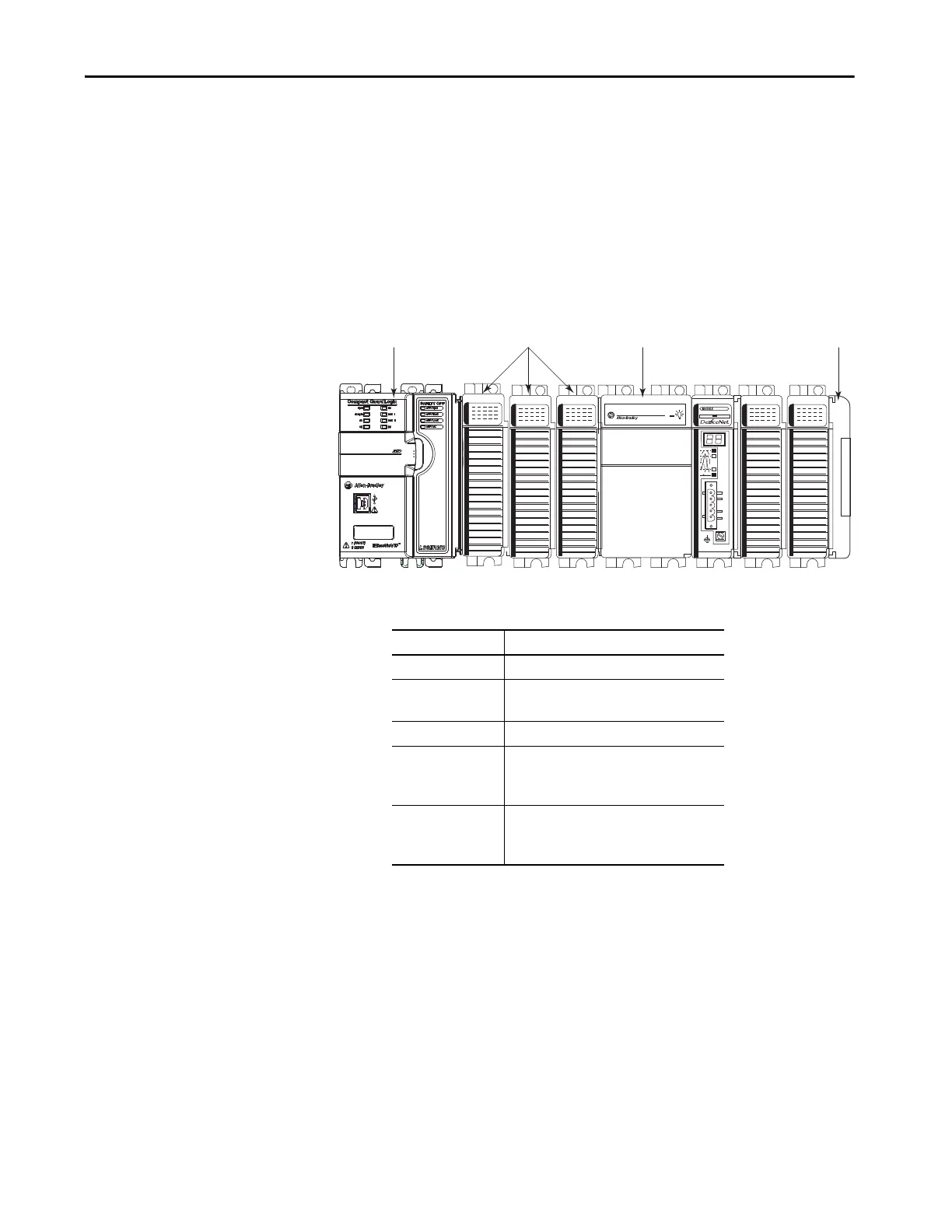
• The controller has a power supply distance rating of four. This rating
means that the controller must be within four slots of the power supply.
You can install as many as three modules between the power supply and
the controller, as shown in the following graphic.
• The controllers support this many local expansion modules across
multiple I/O banks.
• Each I/O bank requires its own power supply.
• You must terminate the end of the last bank in a Compact GuardLogix
5370 controller system. You can terminate a bank at the left or right end
of the bank dependent upon your system design.
A 1769-ECx end cap is required to terminate the end of the last bank in
the control system.
For example, if a Compact GuardLogix 5370 controller system uses one
bank, you must use a 1769-ECR right end cap to terminate the right end
of the bank.
Compact GuardLogix
5370 Controller
Compact I/O Modules End CapPower Supply
Cat. No. Local Expansion Modules Supported, max
1769-L30ERMS 8
1769-L33ERMS
1769-L33ERMSK
16
1769-L33ERMOS —
1769-L36ERMS
1769-L37ERMS
1769-L38ERMS
30
1769-L36ERMOS
1769-L37ERMOS
(1)
1769-L38ERMOS
(1)
(1) Available at firmware revision 31.
—
 Loading...


