86 Rockwell Automation Publication 1769-UM022C-EN-P - June 2018
Chapter 6 Add and Configure Standard I/O Modules
Consider the following when you use distributed I/O modules over a
DeviceNet network:
• Studio 5000® environment - For more information, see
Configure Standard Distributed I/O Modules on an EtherNet/IP
Network on page 98.
• RSNetWorx™ for DeviceNet software - For more information, see
DeviceNet Network Communication
on page 79.
• For information to add distributed I/O modules to your Compact
GuardLogix 5370 controller system, see Configure Standard
Distributed I/O Modules on a DeviceNet Network on page 100.
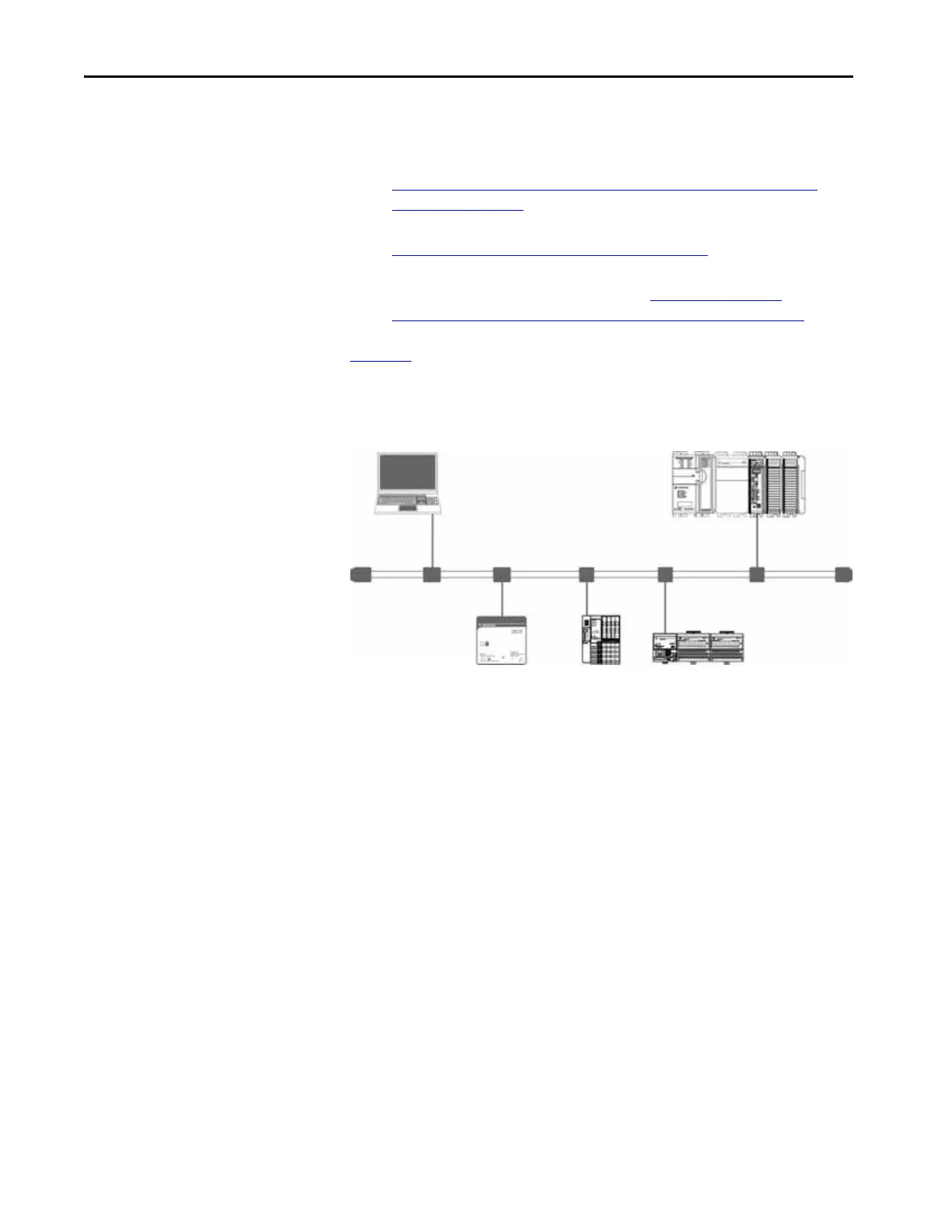
Figure 15
shows an example 1769-L33ERMS controller system that uses local
expansion modules and standard distributed I/O modules over a DeviceNet
network.
Figure 15 - Example 1769-L33ERMS Controller System With Modules Over a DeviceNet Network
Validate Standard I/O Layout
After you have selected your I/O modules, you must validate the system that you
want to design. Consider these points when validating I/O layout placement:
• Estimate Requested Packet Interval
• Module Fault Related to RPI Estimates
•Calculate System Power Consumption
•Power Supply Distance Rating
• Physical Placement of I/O Modules
Standard Distributed I/O Modules
Local Expansion
Modules
DeviceNet Network
 Loading...


