Rockwell Automation Publication 5069-IN019C-EN-P - October 2018 9
CompactLogix 5480 Controller
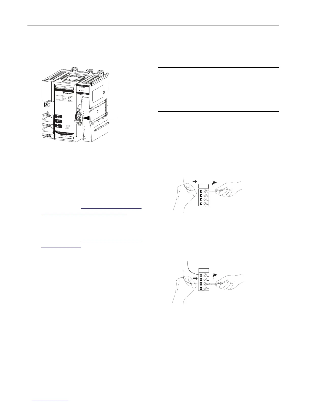
Install the MOD Power RTB
1. Hook the bottom of the MOD power RTB on the controller.
2. Push the RTB against the controller until you hear a click.
.
3. Push the RTB handle against the RTB until you hear a click.
Connect MOD Power
The way that you connect power to the MOD power RTB depends on
whether you use UPS control signals or not.
• If you are not using UPS control signals, you connect the
external power supply directly to the MOD power RTB.
In this case, proceed to
Connect to the MOD Power RTB
from a Standard External Power Supply on page 9.
• If you are using UPS control signals, you connect a UPS to the
MOD power RTB.
In this case, proceed to
Connect to the MOD Power RTB
from a UPS on page 14.
Connect to the MOD Power RTB from a Standard External Power Supply
Before you connect an external power source to the MOD power RTB,
make sure that the MOD power source is properly sized.
1. Verify that the external power supply is not powered.
2. Strip 12 mm (0.47 in.) of insulation from the wires that you
connect to the RTB.
3. Insert the wire from the 24V DC (+) connection on the
external power supply into the first MOD (+) terminal on
the RTB.
4. Turn the screwdriver to close the terminal on the wire.
The screw torque is 0.4 N•m (3.5 lb•in).
5. Insert the wire from the 24V DC (—) connection on the
external power supply into the first MOD (—) terminal on
the RTB.
6. Turn the screwdriver to close the terminal on the wire.
The screw torque is 0.4 N•m (3.5 lb•in).
MOD Power RTB
IMPORTANT Your application can require a power control device, for example,
a switch, between the external 24V DC power source and the
controller to control when the controller is powered. If so, you
must install the power control device at the VDC+ terminal on
the RTB.
If you install the power control device at the VDC- terminal, the
controller can fail to power up or power down properly.

 Loading...


