ControlLogix Voltage/Current Input Module 11
Publication 1756-IN040C-EN-P - October 2000
After completing field-side wiring, secure the wires in the strain relief
area with a cable-tie.
40914-M
12
34
56
78
910
1112
1314
1516
1718
1920
2122
2324
2526
2728
2930
3132
3334
3536
i
i
A
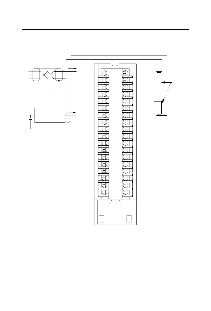
1. All terminals marked RTN are connected internally.
2. For current applications, all terminals marked iRTN must be wired to terminals
marked RTN.
3. A 249Ω current loop resistor is located between IN-x and i RTN-x terminals.
4. Place additional loop devices (e.g. strip chart recorders, etc.) at either A location.
5. If separate power sources are used, do not exceed the specified isolation voltage.
hield ground
Channel 0
Channel 5
Jumper
wires
2-Wire
Transmitter
IN-0
IN-1
IN-2
IN-3
IN-7
RTN
IN-4
IN-5
IN-6
Not used
Not used
Not used
Not used
Not used
Not used
Not used
Not used
Not used
i RTN-0
i RTN-1
i RTN-2
i RTN-3
i RTN-7
RTN
i RTN-4
i RTN-5
i RTN-6
Not used
Not used
Not used
Not used
Not used
Not used
Not used
Not used
Not used
1756-IF8 Single-ended current wiring example
NOTES:
 Loading...


