8 ControlLogix Voltage/Current Input Module
Publication 1756-IN040C-EN-P - October 2000
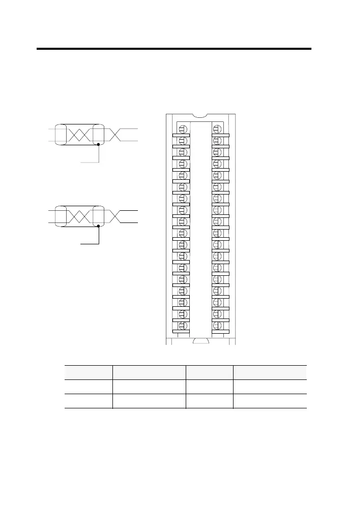
Wire the Module
You can only connect wiring to your module through an RTB or IFM.
The example below shows how to wire the module.
12
34
56
78
910
1112
1314
1516
1718
1920
2122
2324
2526
2728
2930
3132
3334
3536
+
–
+
–
1756-IF8 Differential voltage wiring example - 4 channels
40913-M
Shield ground
Channel 0
Channel 3
IN-0
IN-1
IN-2
IN-3
IN-7
RTN
IN-4
IN-5
IN-6
Not used
Not used
Not used
Not used
Not used
Not used
Not used
Not used
Not used
i RTN-0
i RTN-1
i RTN-2
i RTN-3
i RTN-7
RTN
i RTN-4
i RTN-5
i RTN-6
Not used
Not used
Not used
Not used
Not used
Not used
Not used
Not used
Not used
Shield ground
1. Use the following chart when wiring your module in differential mode
2. When operating in 2 channel, high speed mode, only use channels 0 and 2.
3. All terminals marked RTN are connected internally.
4. A 249Ω current loop resistor is located between IN-x and i RTN-x terminals.
5. If multiple (+) or multiple (-) terminals are tied together, connect that tie point to a RTN
terminal to maintain the module’s accuracy.
6. Place additional loop devices (e.g. strip chart recorders, etc.) at either A location.
7. If separate power sources are used, do not exceed the specified isolation voltage.
This channel: Uses these terminals: This channel: Uses these terminals:
Channel 0 IN-0, IN-1 & i RTN-0 Channel 2 IN-4, IN-5 & i RTN-4
Channel 1 IN-2, IN-3 & i RTN-2 Channel 3 IN-6, IN-7 & i RTN-6
NOTES:
 Loading...


