ControlLogix Voltage/Current Input Module 9
Publication 1756-IN040C-EN-P - October 2000
2
4
6
8
10
12
14
16
18
20
22
24
26
28
30
32
34
36
i
i
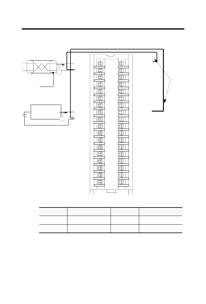
1756-IF8 Differential current wiring example - 4 channels
A
A
40912-M
Shield
ground
Channel 0
Channel 3
Jumper
wires
2-Wire
Transmitter
IN-0
IN-1
IN-2
IN-3
IN-7
RTN
IN-4
IN-5
IN-6
Not used
Not used
Not used
Not used
Not used
Not used
Not used
Not used
Not used
1
3
5
7
9
11
13
15
17
19
21
23
25
27
29
31
33
35
i RTN-0
i RTN-1
i RTN-2
i RTN-3
i RTN-7
RTN
i RTN-4
i RTN-5
i RTN-6
Not used
Not used
Not used
Not used
Not used
Not used
Not used
Not used
Not used
1. Use the following chart when wiring your module in differential mode
2. When operating in 2 channel, high speed mode, only use channels 0 and 2.
3. All terminals marked RTN are connected internally.
4. A 249Ω current loop resistor is located between IN-x and i RTN-x terminals.
5. If multiple (+) or multiple (-) terminals are tied together, connect that tie point to a RTN
terminal to maintain the module’s accuracy.
6. Place additional loop devices (e.g. strip chart recorders, etc.) at either A location.
7. If separate power sources are used, do not exceed the specified isolation voltage.
This channel: Uses these terminals: This channel: Uses these terminals:
Channel 0 IN-0, IN-1 & i RTN-0 Channel 2 IN-4, IN-5 & i RTN-4
Channel 1 IN-2, IN-3 & i RTN-2 Channel 3 IN-6, IN-7 & i RTN-6
NOTES:
 Loading...


