Rockwell Automation Publication 1606-RM008A-EN-P - November 2021 11
DC-UPS - 24V, 20 A, 480 W Reference Manual
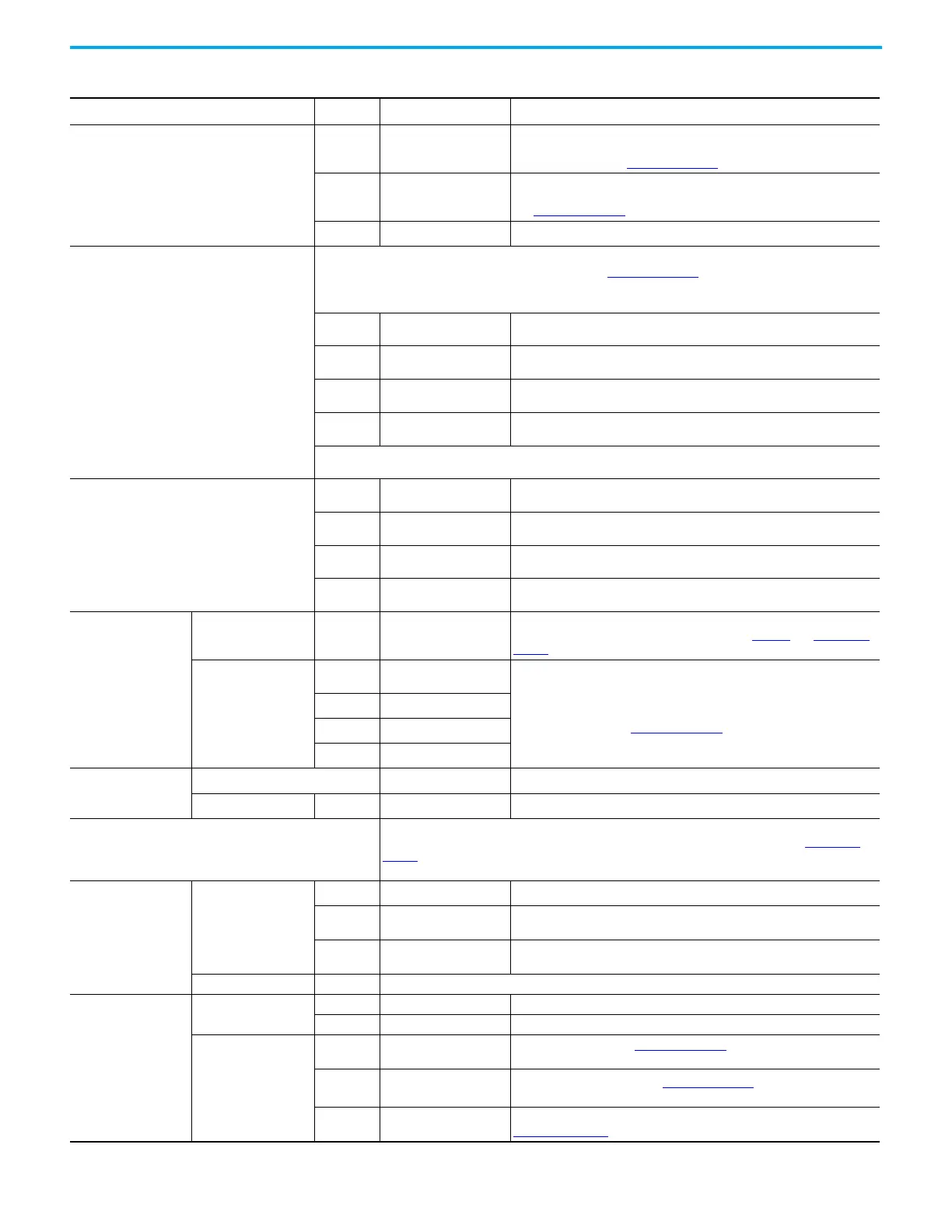
Input voltage Nom DC 24V -±25%
Input voltage range
Nom
18…30V DC
Control functions such as light-emitting diode (LEDs), monitoring features,
relay contacts, etc. are working. The unit can either be in power supply mode
or in battery mode. See Figure 3 on page 10
.
Max 30…35V DC
Temporarily allowed, no damage to the DC-UPS. The red error light-emitting
diode (LED) reports “Input Voltage”, charging and buffering are not possible.
See Figure 3 on page 10.
Max
35V DC Absolute max voltage with no damage to the unit.
Normal operating input voltage ranges
Ranges, where the unit does not switch to battery mode. See Figure 3 on page 10
. Please note: The lower end must be
at least 1V higher than buffer voltages settings.
Typ.
23.5…30V DC
Range A for a 22.5V buffer voltage setting
Typ
25…30V DC
Range B for a 24V buffer voltage setting
Typ
26…30V DC
Range C for a 25V buffer voltage setting
Typ
27…30V DC
Range D for a 26V buffer voltage setting
Important: The lower end must be at least 1V higher than buffer voltages settings.
Transfer voltage for switching into battery mode
Typ
23.5V DC
Range A, 22.5V buffer voltage
Typ
25V DC
Range B, 24V buffer voltage
Typ
26V DC
Range C, 25V buffer voltage
Typ
27V DC
Range D, 26V buffer voltage
Output voltage
in power supply mode Typ
0.12V less than input
voltage at 20 A
The output voltage is always slightly lower than the input voltage,
independent of the value of the input voltage. See Figure 5
and Figure 6 on
page 12
in battery mode
Nom
22.5V DC
±3%
The buffer voltage is the output voltage in battery mode, selectable in four
steps via rotary switch on the front of the unit and will not change as the
batteries discharge. See Figure 3 on page 10.
Nom
24.0V DC±3%
Nom
25.0V DC±3%
Nom
26.0V DC
±3%
Ripple and noise voltage
in power supply mode
not applicable
better as the supplying power supply (filter included)
in battery mode Max
120mVpp
20 Hz to 20 MHz, 50 Ohm
Requirements for the power supply on the input
- Use an appropriately sized 24V power supply, which can deliver the additional required internal current
consumption of the DC-UPS and the required current for charging the batteries. See also Figure 7 on
page 12
- Use power supplies that do not deliver more than 28 A continuous output current 1).
Input Current
internal consumption
Typ
80 mA
When batteries are fully charged
Max 2.1 A / 4.0 A
For <10 Ah / >10 Ah settings; during battery charging,
no temperature sensor installed
Max 2.3 A / 4.3 A
For <10 Ah / >10 Ah settings; during battery charging,
temperature sensor is installed
total input current Max Sum of the output (load) current and the internal current consumption
Output Current
in power supply mode
Nom 25 A Continuously allowed
Nom 30 A For max 5 s
in battery mode
Nom 20 A at 22.5V, 18 A at 26V
Continuously allowed see Figure 8 on page 12
(interpolate linearly between
22.5V and 26V)
Nom 30 A at 22.5V, 26 A at 26V
For typ 4 s (BonusPower
(1)
) see Figure 7 on page 12 (interpolate linearly
between 22.5V and 26V)
Typ 80 A
For typ. 25 ms, output voltage stays above 20V, (dynamic peak current), see
Figure 10 on page 12
.
 Loading...