Rockwell Automation Publication 1606-RM008A-EN-P - November 2021 19
DC-UPS - 24V, 20 A, 480 W Reference Manual
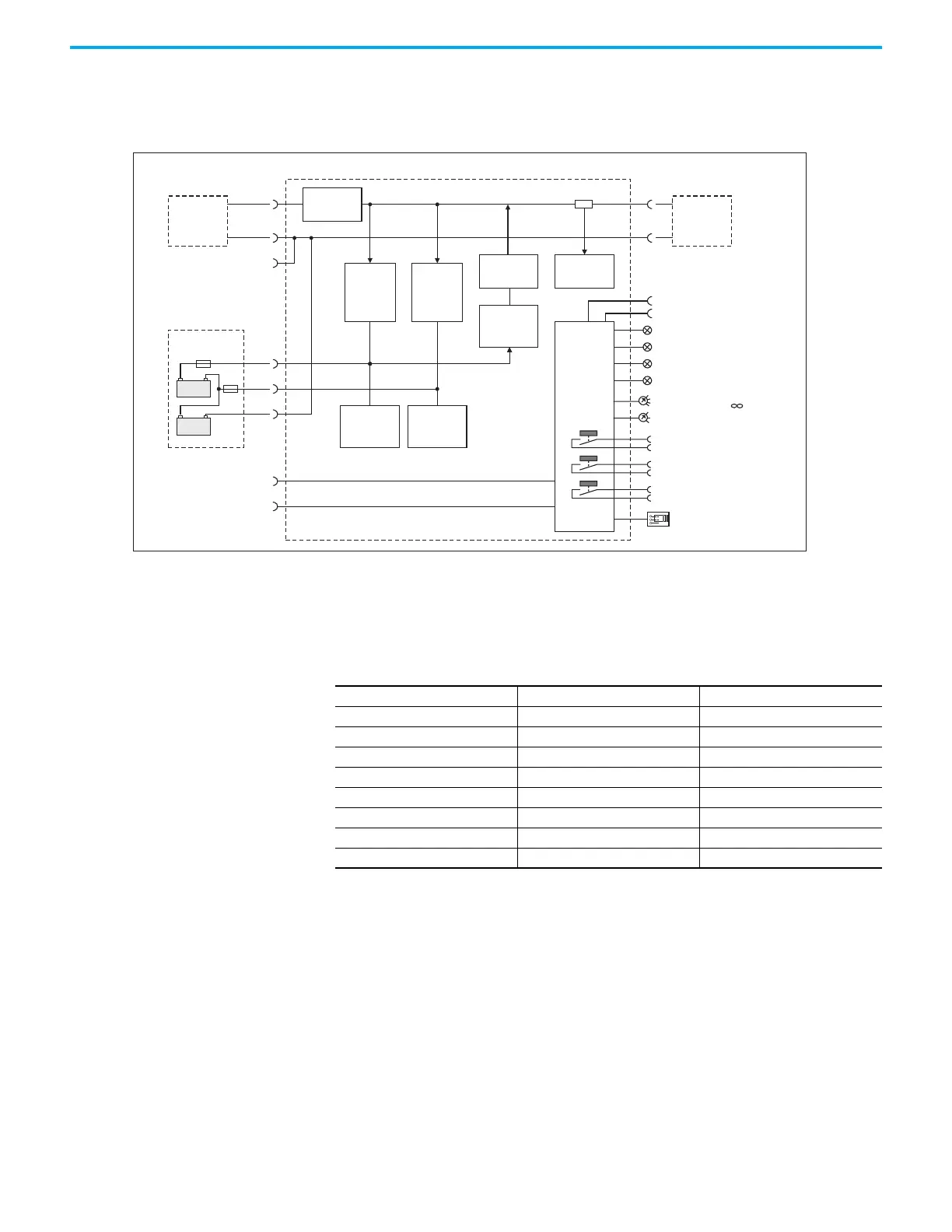
Functional Diagram Figure 14 - Functional Diagram
Terminals and Wiring The terminals are IP20 fingersafe constructed and suitable for field and
factory wiring.
Instructions:
1. Use appropriate copper cables that are designed for minimum operating
temperatures of:
• 60 °C for ambient up to 45 °C and
• 75 °C for ambient up to 60 °C and
• 90 °C for ambient up to 70 °C minimum
2. Follow national installation codes and installation regulations.
3. Verify that all strands of a stranded wire enter the terminal connection.
4. Unused terminal compartments should be securely tightened or closed.
5. Ferrules are allowed.
DC- UPS
24V
Power
Supply
Buck/Boost
Converter
Battery
Charger
1
Battery
Diagnosis
1
+
-
24V
Battery
+
-
Input
Batt
+-
BAT2
12V
+-
BAT1
12V
CT
Battery
Charger
2
Current
Limiter
Battery
Diagnosis
2
(13)
-
Current
Measure-
ment
+
-
Buffered
Load
Output
Diagnosis LED
(yellow)
Status LED
Batt 2 (green)
Inhibit +
Controller
Error LED
(red)
Replace Battery
Buffering
Contact
Ready Contact
Buffer Time Limiter
10s, 30s, 1m, 3m, 10m,
(7)
Inhibit -
(8)
(1)
(2)
(3)
(4)
(5)
(6)
Status LED
Batt 1 (green)
Buffer Voltage
22.5V, 24V, 25V, 26V
Temp. Sensor (11)
Center
Tap
Back
Feeding
Protection
Battery Size Selector
<10Ah / > 10Ah
Temp. Sensor (12)
Batt
Input and Output Signals
Type screw terminals pluggable screw terminals
Solid wire 0.5…6 mm
2
0.2…1.5mm
2
Stranded wire 0.5…4 mm
2
0.2…1.5mm
2
American Wire Gauge AWG 20…10 AWG 22…14
Max wire diameter 2.8 mm (including ferrules) 1.5 mm (including ferrules)
Wire stripping length 7 mm / 0.28 in 6 mm / 0.25 inch
Tightening torque 1 Nm / 9 lb. in 0.4 Nm / 3.5 lb.inch
Screwdriver 3.5 mm slotted or cross-head No 2 3 mm slotted
 Loading...