20 Rockwell Automation Publication 1606-RM008A-EN-P - November 2021
DC-UPS - 24V, 20 A, 480 W Reference Manual
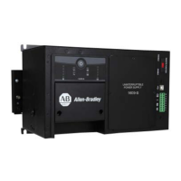
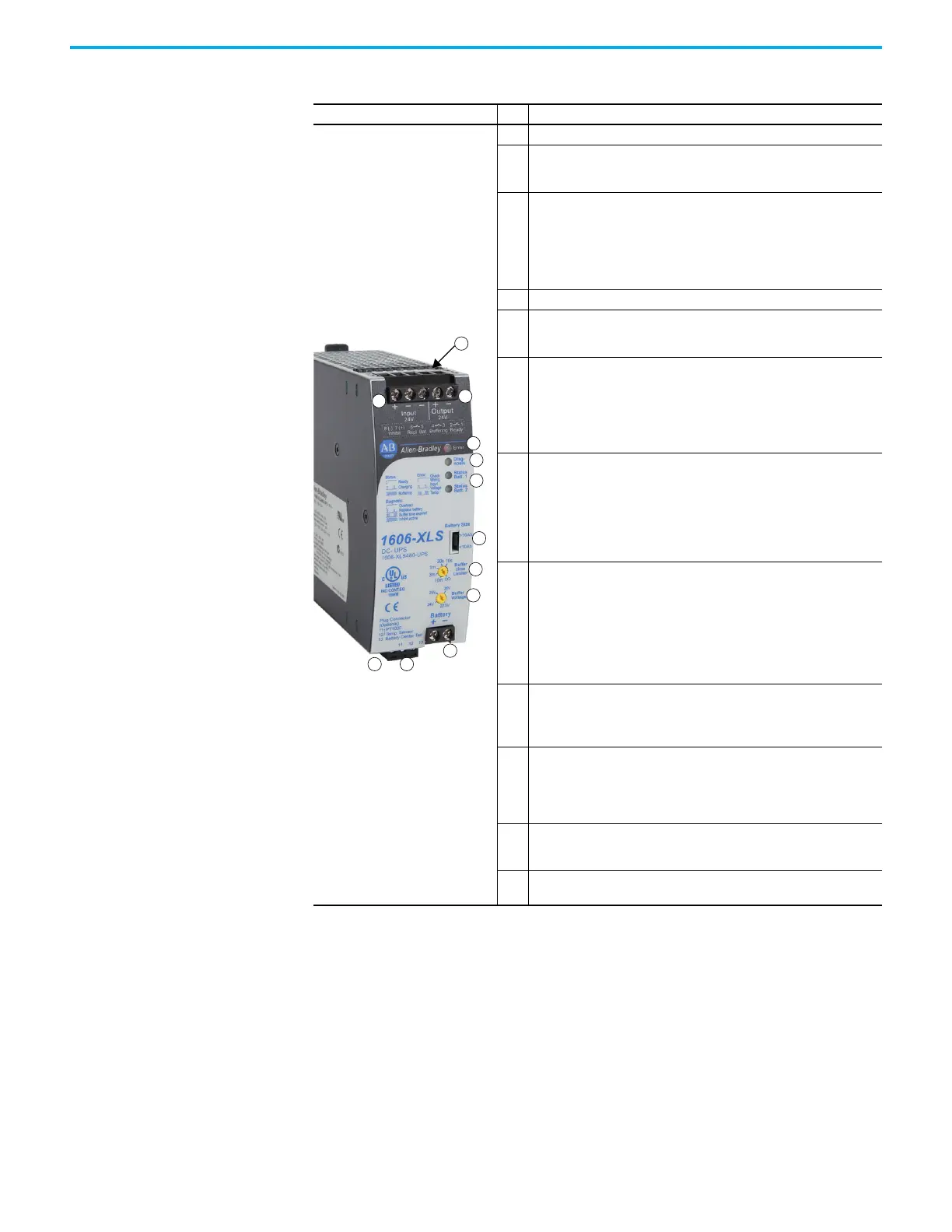
Front User Elements
Photo No. Description
1 Input Terminal (screw terminal)
2
Output Terminal (screw terminal) One extra (-) pole for easy grounding.
The minus-pole is internally hard-wired with the minus-pole of the input
and battery terminals.
3
Signal Connector (8-pole plug connector) comprises the following
connections:
•Ready relay contact
• Buffering relay contact
• Inhibit input signal
• Replace battery
4 Battery Terminal (screw terminal)
5
Battery Monitoring Connector (3-pole plug connector)
- Connection for temperature sensor for battery temperature.
- “Center-Tap” connection - middle point of the two batteries.
6
Red Error light-emitting diode (LED) – This light-emitting diode (LED)
indicates that charging or buffering is not possible.
The updating pattern reports the following reasons:
•Check wiring
• Insufficient input voltage
• Temperature exceeded
7
Yellow Diagnosis light-emitting diode (LED) – This light-emitting diode
(LED) helps troubleshooting and the updating pattern indicates the
following:
• Output overloaded (current)
• Battery replacement required
• Expired buffer time due to buffer time selector or discharged battery
Activated inhibit input
8
Green light-emitting diode (LED) – Each battery has its own status LED.
Battery 1 represents the battery, which is electrically closer to the (+) pole
and battery 2, which is closer to the (-) pole.
The updating pattern of this light-emitting diode (LED) reports the
following information:
•Ready
•Charging
•Buffering
9
Battery Size Selector (pluggable jumper). Two positions to select battery
sizes > and <10 Ah. Influences the charging current, the allowed battery
temperature range and the battery quality tests. Factory set: <10 Ah. A
missing jumper equals a <10 Ah setting.
10
Buffer Time Limiter (rotary switch with 6 dents). Limits the maximum
buffer time in a buffer event to save battery energy. Selectable between
10 s 30s, 60 s, 3 minutes, and 10 minutes. If no limitation is selected
(infinite period), the buffering will end by the deep discharge protection.
Factory set: infinite.
11
Buffer Voltage Selector (rotary switch with 4 dents). Allows setting the
output voltage in battery mode to 22.5V, 24V, 25V, or 26V. Factory set:
22.5V
12
Chassis Ground (screw) Use a M4 ring-type terminal to connect the
housing to ground, when required.
 Loading...