Rockwell Automation Publication 1606-RM008A-EN-P - November 2021 21
DC-UPS - 24V, 20 A, 480 W Reference Manual
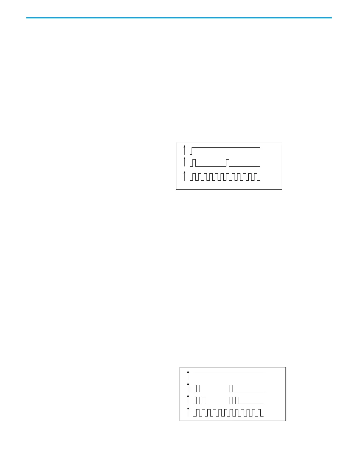
Each battery has its own status indicator. The signals are the same for both
batteries.
Ready: The light-emitting diode (LEDs) are on solid when the battery is
charged (> 85%), no wiring failure is recognized, input voltage is sufficient.
After the unit is turned-on with charged batteries, it can take 20s or longer that
the signal switches from charging to ready.
Charging: The light-emitting diode (LEDs) are updating with a low frequency
when the batteries are charging and the state-of-charge is below 85%.
Buffering: The light-emitting diode (LEDs) are updating with a high frequency
when the unit is in battery mode.
Figure 15 - Flashing pattern for green “Status LED”
This light-emitting diode (LED) helps troubleshooting.
Overload: The light-emitting diode (LED) is on solid when the output current
is permanently above 20 A in battery mode or 25 A in power supply mode.
Replace Battery: The light-emitting diode (LED) is updating with a low
frequency when one battery has failed the periodically performed battery
quality test. In case the center-tap connection is present, the battery that has
failed is indicated by the green light-emitting diode (LED) which is off.
Otherwise, both light-emitting diode (LEDs) are off. The battery should be
replaced as soon as possible.
Buffer time expired: The light-emitting diode (LED) is double updating when
the output has switched off due to the setting of the buffer-time limiter or
discharged battery. This signal will be displayed for 15 minutes after the output
has switched off.
Inhibit active: The light-emitting diode (LED) is updating with a high
frequency when buffering is disabled due to an active inhibit signal.
Figure 16 - Flashing pattern for yellow “Diagnoses Light-emitting Diode (LED)”
0
1
0
Overload
1
0
Replace
Battery
1
0
Buffertime
expired
1
0
Inhibit
active
5
Hz
 Loading...