8 Rockwell Automation Publication 1606-RM008A-EN-P - November 2021
DC-UPS - 24V, 20 A, 480 W Reference Manual
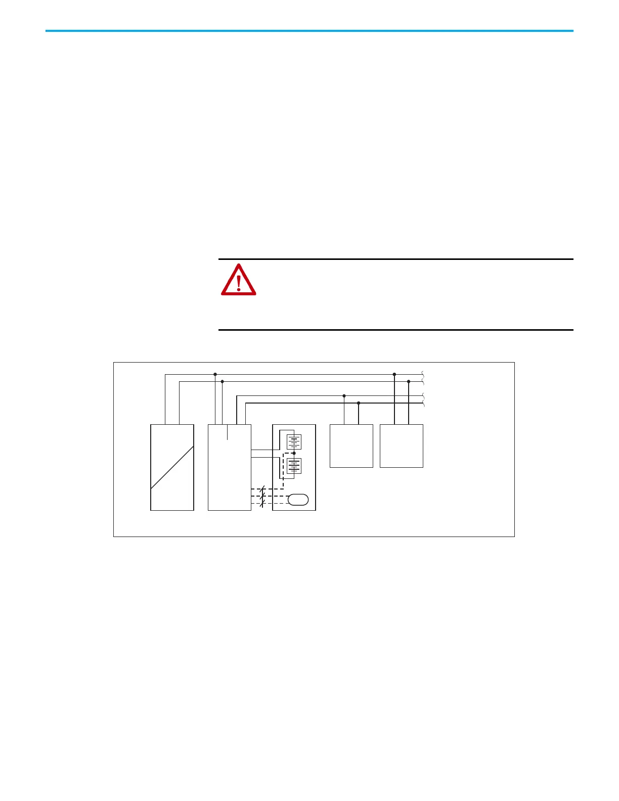
• Use a 4 A fuse (ATOF® 287 004 from Little fuse or an UL Listed fuse with
same characteristics) between the connection point of the two 12V
batteries and the “Center Tap” connection point of the DC-UPS. An
equivalent protection is included on the original battery modules. The
center tap connection is not mandatory but enables an individual
charging and monitoring of the two batteries.
• Optionally, a PT1000 temperature sensor can be connected to terminals
point 11 and 12 to measure the battery temperature. This adjusts the
charging voltage according to the battery temperature, which extends
the battery life. This sensor is already installed in the original battery
modules.
Installation Instructions for Hazardous Location Areas
• The device is suitable for use in Class I Division 2 Groups A, B, C, D
locations and for use in Group II Category 3 (Zone 2) environments.
• Hazardous Location Classification: ATEX: EPS 15 ATEX 1 025 X, II 3G EX
EC nC IIC T4 Gc
Figure 1 - Typical Wiring Diagram
WARNING: Explosion Hazards
• Substitution of components may impair suitability for this environment.
• Do not disconnect the device or change unit settings unless power has been
switched off or the area is known to be non-hazardous.
• A suitable enclosure must be provided for the end product, which has a
minimum protection of IP54 and, fulfills the requirements of the EN 60079-
24V Power
Supply
+
-
Input
+
-
+
-
24V Battery
Module
+
Buffered
Load
+
-
Non-
buffered
Load
+
-
24V
buffered
branches
24 V
Non-bufferd
branches
Temp.
Sensor
Output
Battery
-
Bat1
12V
Bat2
12V
Center Tap
Temp. Sensor
DC-UPS
AC
DC
Output
Input
NLPE
+
+
optional
 Loading...