Rockwell Automation Publication 2080-UM001B-EN-E - November 2011 15
Chapter
3
Install Your Controller
Controller Mounting
Dimensions
Mounting Dimensions
Mounting dimensions do not include mounting feet or DIN rail latches.
Micro810 Controllers
2080-LC10-12AWA, 2080-LC10-12QWB, 2080-LC10-12QBB,
2080-LC10-12DWD
Module Spacing
Maintain spacing from objects such as enclosure walls, wireways and adjacent
equipment. Allow 50.8 mm (2 in.) of space on all sides for adequate ventilation.
An exception to this spacing guideline is allowed for the side at which you are
connecting the optional power supply, 2080-PS120-240VAC.
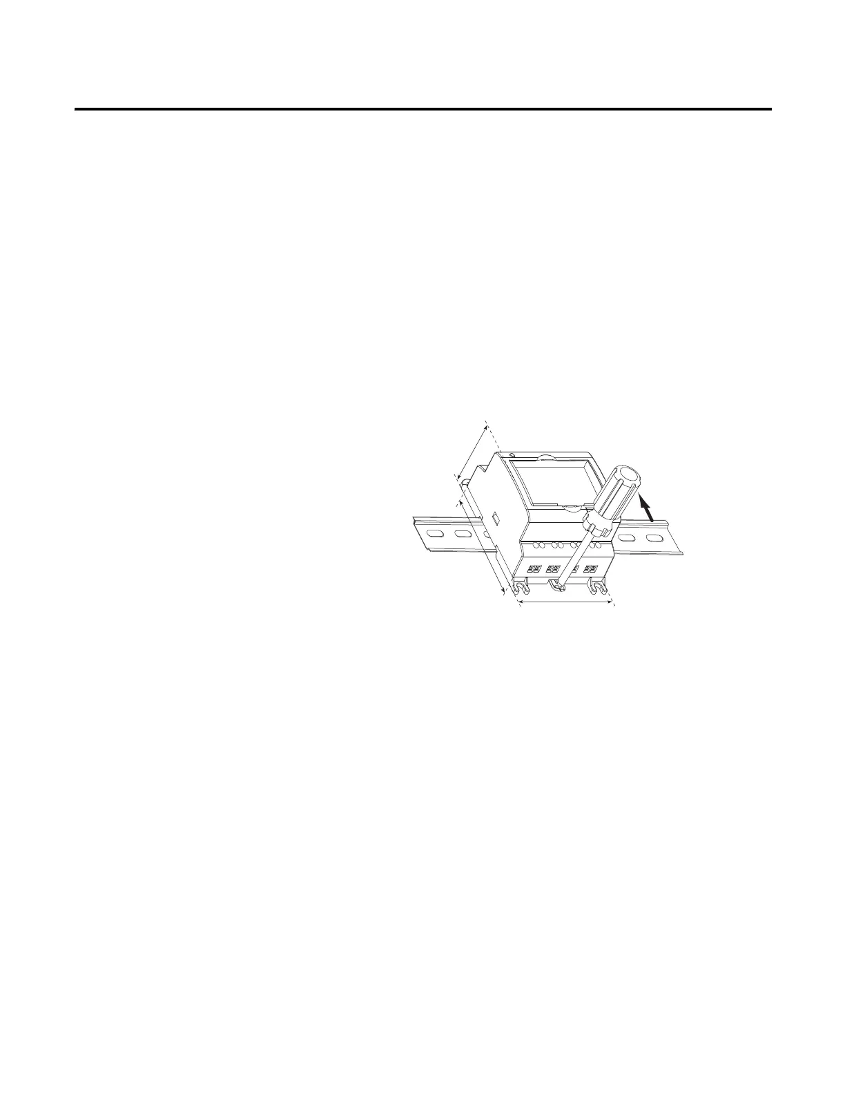
DIN Rail Mounting
The module can be mounted using the following DIN rails: 35 x 7.5 mm x 1 mm
(EN 50 022 - 35 x 7.5).
Before mounting the module on a DIN rail, use a flat-blade screwdriver in the
DIN rail latch and pry it downwards until it is in the unlatched position.
For environments with greater vibration and shock concerns, use the
panel mounting method, instead of DIN rail mounting.
45054
74.85 mm (2.95 in.)
59 mm (2.32 in.)
91 mm (3.58 in.)