Rockwell Automation Publication 2080-UM001B-EN-E - November 2011 89
Quickstarts Appendix E
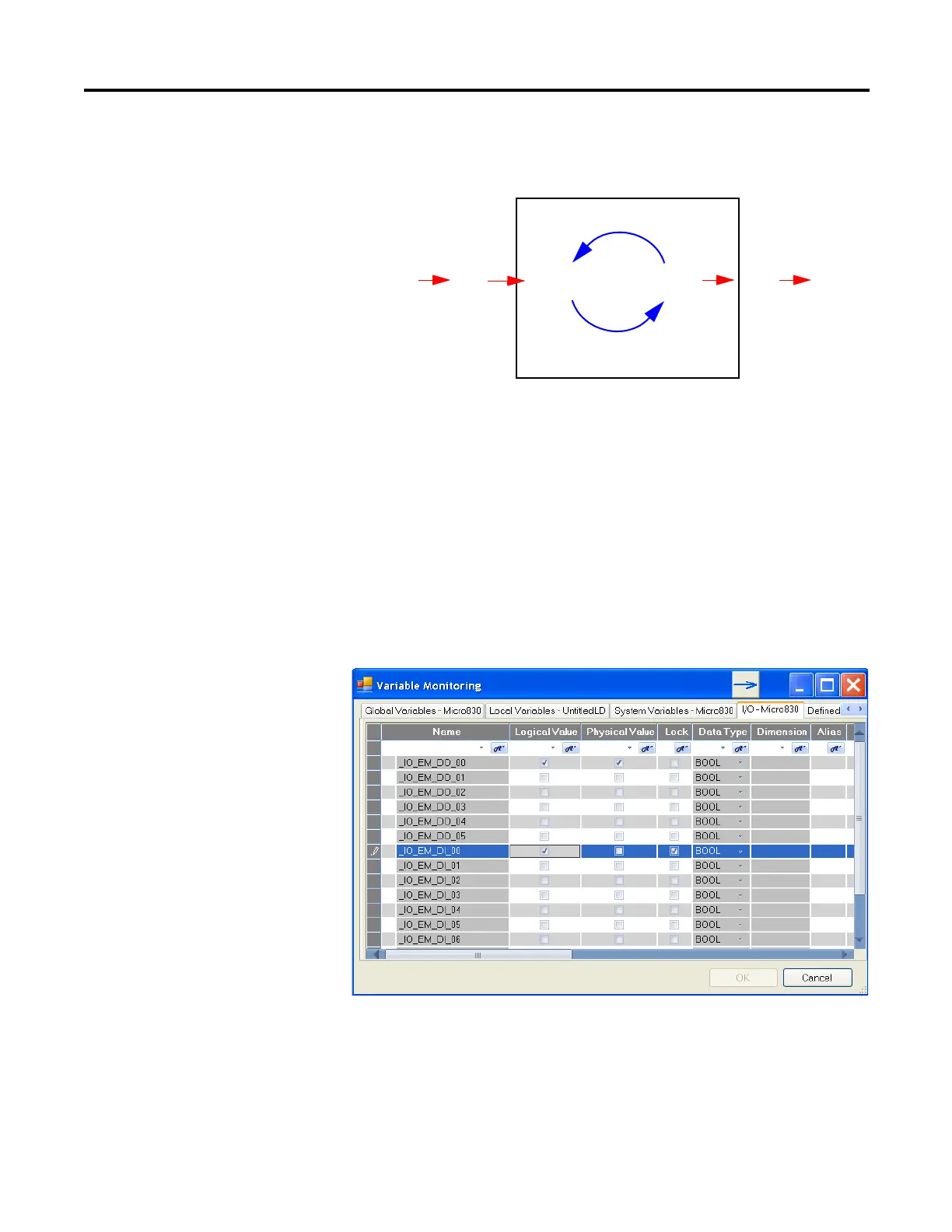
The following diagram illustrates forcing behaviour.
Check if Forces (locks) are Enabled
If Connected Components Workbench (CCW) is available, check the Variable
Monitor while debugging online. Forcing is performed by first Locking an I/O
variable and then setting the Logical Value for Inputs and Physical Value for
Outputs. Remember you cannot force a Physical Input and cannot force a Logical
Output.
In many cases, the front of the controller is not visible to the operator and CCW
is not online with the controller. If you want the force status to be visible to the
operator, then the User Program must read the force status using the SYS_INFO
function block and then display the force status on something that the operator
can see, such as the human machine interface (HMI), or stack light. The
User Program
Logical
Inputs
Logical
Outputs
Normal
Variables
Force
Physical
Inputs
Force
Physical
Outputs
• LED status indicators always match the phyical value of I/O
• Normal, non-physical internal variables cannot be forced