Rockwell Automation Publication 2080-UM005B-EN-E - March 2015 117
Specifications Chapter A
PWM Output Duty Cycle Error
Turn On/Off time for the Micro820 controllers for the PWM output port is
0.2 μs and 2.5 μs max, respectively. Duty cycle error is:
Positive error = 2.5 μs * F
Negative error = -0.2 μs * F
The plot below shows duty cycle error vs. frequency.
To get the duty cycle error at a certain frequency, for example, the user sets
frequency to 20 KHz, and sets duty cycle to 30% in Connected Components
Workbench, then actual duty cycle is
Current ratings per point 0.3 A @ 65 °C, max
1.0 A @ 30 °C, max
1.0 mA, max leakage
100 mA (high speed
operation)
1.0 A @ 30 °C
0.3 A @ 65 °C
(standard operation)
1.0 mA, max leakage
Surge current per point
peak current
max surge duration
max rate of repetition @ 30 °C
max rate of repetition @ 65 °C
4.0 A
10 ms
once each second
once every two seconds
Controller current, max total 3 A –
Turn-on time, max 0.1 ms 0.2 μs
Turn-off time, max 1.0 ms 2.5 μs
Response time, max 10 ms
Frequency rate NA 2%
(1) High speed output operation is greater than 5 Khz.
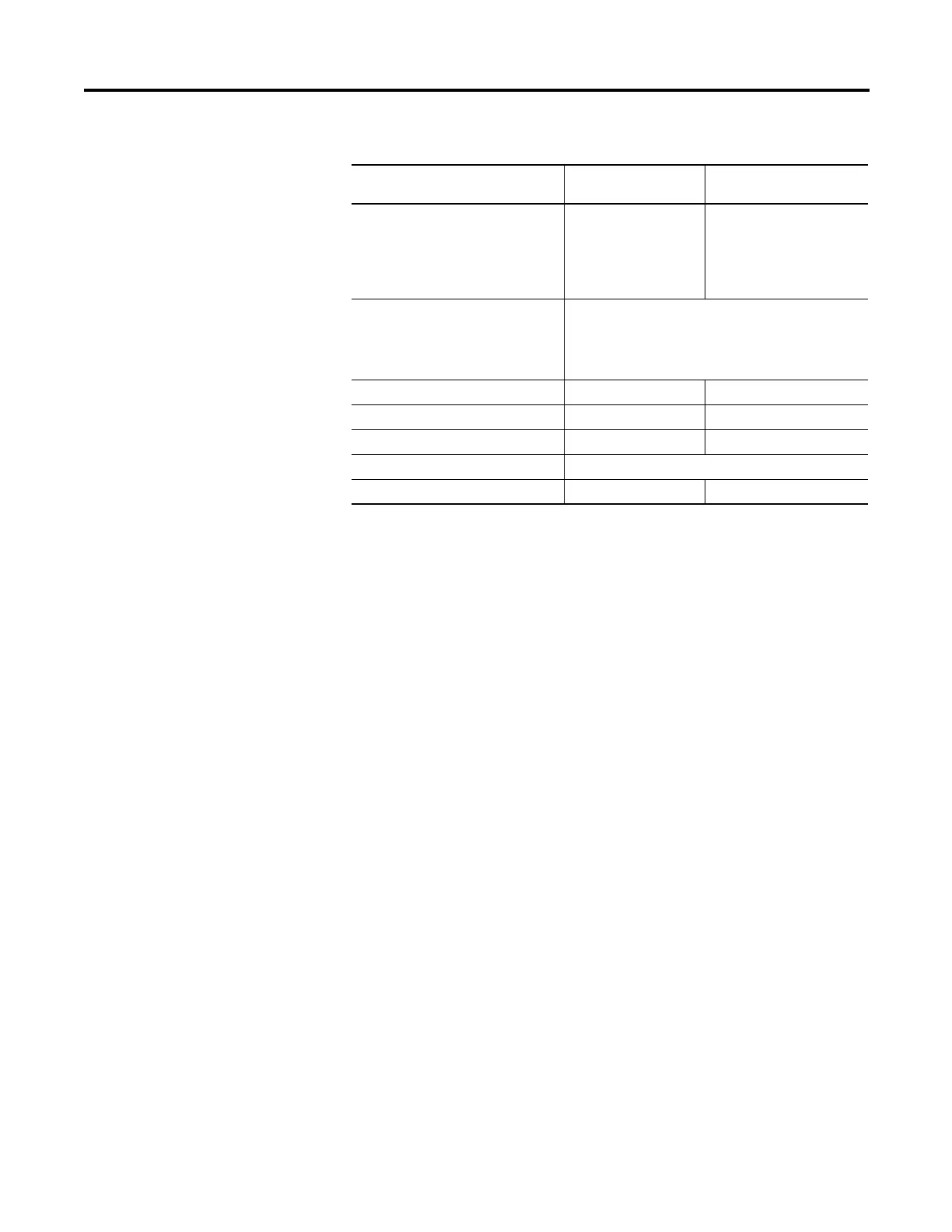
DC Output Specifications for 2080-LC20-20QBB(R)
Attribute Standard Outputs
(Outputs O-00…O-05)
High Speed Output
(1)
(Output O-06)

 Loading...


