EasyManuals Logo

Allen-Bradley Micro820 User Manual

Allen-Bradley Micro820
184 pages
To Next Page IconTo Next Page
To Previous Page IconTo Previous Page
Page #51 background imageLoading...
Page #51 background image
Rockwell Automation Publication 2080-UM005B-EN-E - March 2015 43
Wire Your Controller Chapter 4
Wiring Analog Channels
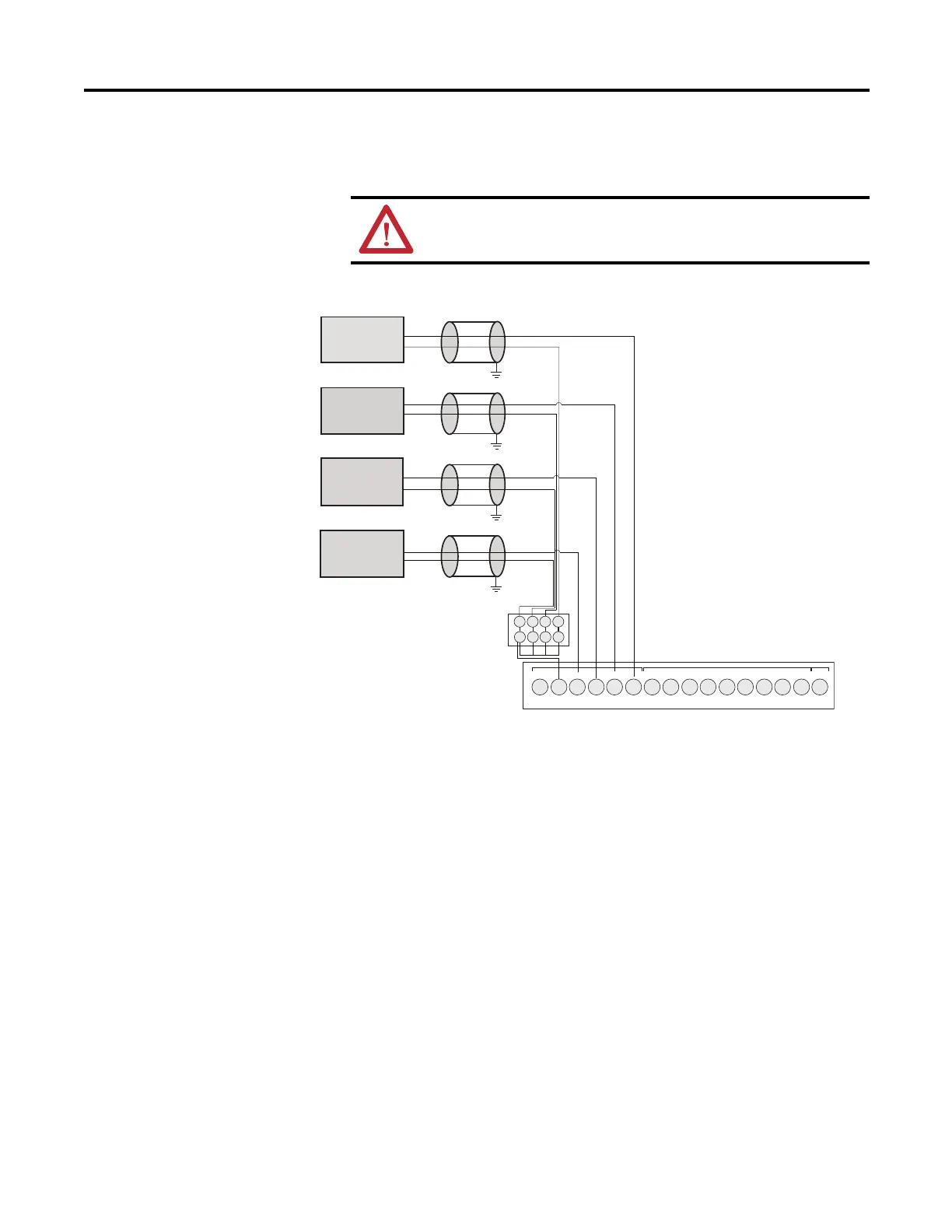
Analog input circuits can monitor voltage signals and convert them to serial
digital data as shown in the following illustration.
Analog input to sensors
ATTENTION: Analog inputs and outputs are not isolated.
Sensor 3
(V) Voltage
Sensor 2
(V) Voltage
Sensor 1
(V) Voltage
Sensor 0
(V) Voltage
-DC24
+DC10 I-00
I-01
I-02
I-03
COM0
I-04
I-05
I-08
I-07
123456789101112
I-10
I-09
NU
I-11
13 14 15 16
I-06
1234
1234
46254
Note: Terminal block to wire
commons is not included in
Micro800 package.
The “-DC24” terminal is the analog ground connection for analog inputs (I-00 to I-03).

Table of Contents

Other manuals for Allen-Bradley Micro820

Questions and Answers:

Question and Answer IconNeed help?

Do you have a question about the Allen-Bradley Micro820 and is the answer not in the manual?

Allen-Bradley Micro820 Specifications

General IconGeneral
Processor32-bit
Power Supply24V DC
Programming SoftwareConnected Components Workbench
SeriesMicro800
MountingDIN Rail
MemoryEmbedded
ExpansionYes
Controller TypeProgrammable Logic Controller (PLC)
CommunicationEthernet/IP
Programming LanguageLadder Diagram, Function Block Diagram, Structured Text
I/OEmbedded

Related product manuals