44 Rockwell Automation Publication 2080-UM005B-EN-E - March 2015
Chapter 4 Wire Your Controller
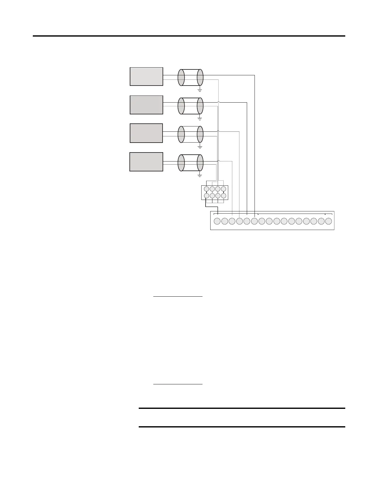
Analog input to thermistors
Calculate for Thermistor Resistance
While connecting Analog input to thermistor as shown in previous diagram,
calculate input voltage using the following equation:
Where:
Vi = Voltage input (±5% without calibration; ±2% with calibration)
Ri = Resistance input (14.14 KΩ ±2%)
Rt = Thermistor resistance (10 KΩ Thermistor is recommended)
Vref = 10V ±0.5V
To calculate for thermistor resistance, use the following equation.
-DC24
+DC10 I-00
I-01
I-02
I-03
COM0
I-04
I-05
I-08
I-07
123456789101112
I-10
I-09
NU
I-11
13 14 15 16
I-06
Thermistor 3
Thermistor 2
Thermistor 1
Thermistor 0
1234
1234
46255
Note: Terminal block to wire
commons is not included in
Micro800 package.
The “+DC10” terminal supplies 10V DC power source to the Thermistor inputs (I-00 to I-03).
Micro820 controllers support 10 KΩ type thermistors.
In order to get the best results, the system must be calibrated.

 Loading...


