Rockwell Automation Publication 2080-UM005B-EN-E - March 2015 45
Wire Your Controller Chapter 4
Calibrate Thermistor
1. Connect a resistor (10 KΩ is recommended) across Vref and Analog
Input 00 of your Micro820 controller following the diagram, Analog input
to thermistors on page44. The resistor is measured as Ri using a precision
multimeter.
2. Calculate the ideal counts (C1) for resistor (Ri) following this equation:
C1 = 14.14 KΩ / (14.14 KΩ + Ri) * 4095
3. Read the actual counts (C2) of Analog Input 00 from Connected
Components Workbench.
4. Calculate for calibration Gain.
Gain = C1/C2
For example:
If Ri is measured as 10.00 KΩ, then
C1 = 14.14 / (14.14 + 10.00) * 4095 = 2399 counts;
C2 is read from Connected Components Workbench as 2440; so
Gain = 2399/2440 = 98% .
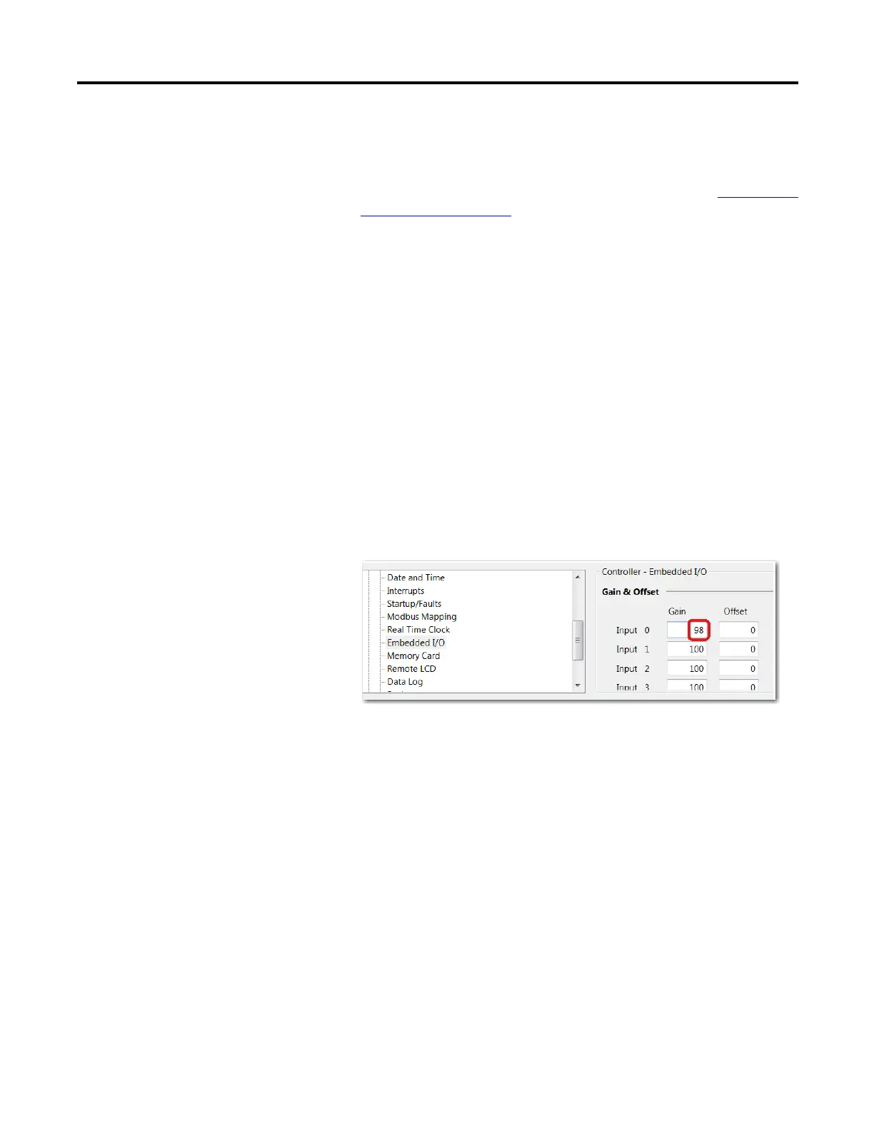
5. In Connected Components Workbench, go to Embedded I/O
configuration page. Change the Gain parameter value for Input 00 to 98.
No changes are required to the Offset parameter value.
6. Repeat the same steps to calibrate all the other analog input channels.

 Loading...


