Using Math Instructions
8–13
The following example takes a 0V to 10V analog input from a MicroLogix 1000
analog controller and scales the raw input data to a value between 0 and 100%. The
input value range is 0V to 10V which corresponds to 0 to 31,207 counts. The scaled
value range is 0 to 100 percent.
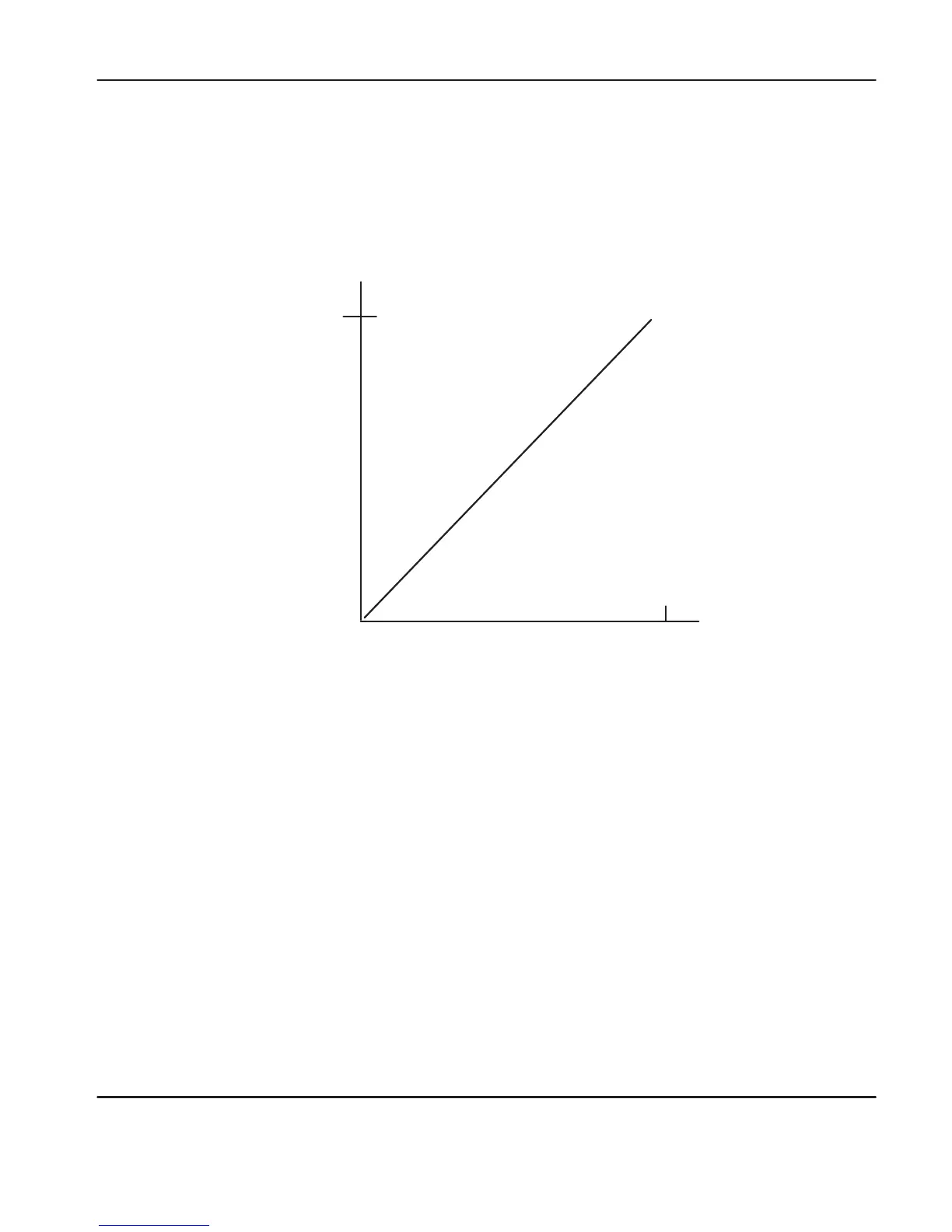
Application Example – Convert Voltage Input to Percent
Scaled Value
(percent)
Input Value
0V
31,207 10V
100
(Scaled Max.)
(Scaled Min.)
(Input Min.) (Input Max.)
0
Calculating the Linear Relationship
Use
the following equations to calculate the scaled units:
Scaled value = (input value x rate) + offset
Rate = (scaled max. – scaled min.) / (input max. – input min.)
= (100 – 0) / (31,207 – 0)
= .00320 (or 32/10000)
Offset = scaled min. – (input min. x rate)
= 0
− (0 × .00320) = 0
efesotomasyon.com - Allen Bradley,Rockwell,plc,servo,drive

 Loading...


