Using High-Speed Counter Instructions
12–19
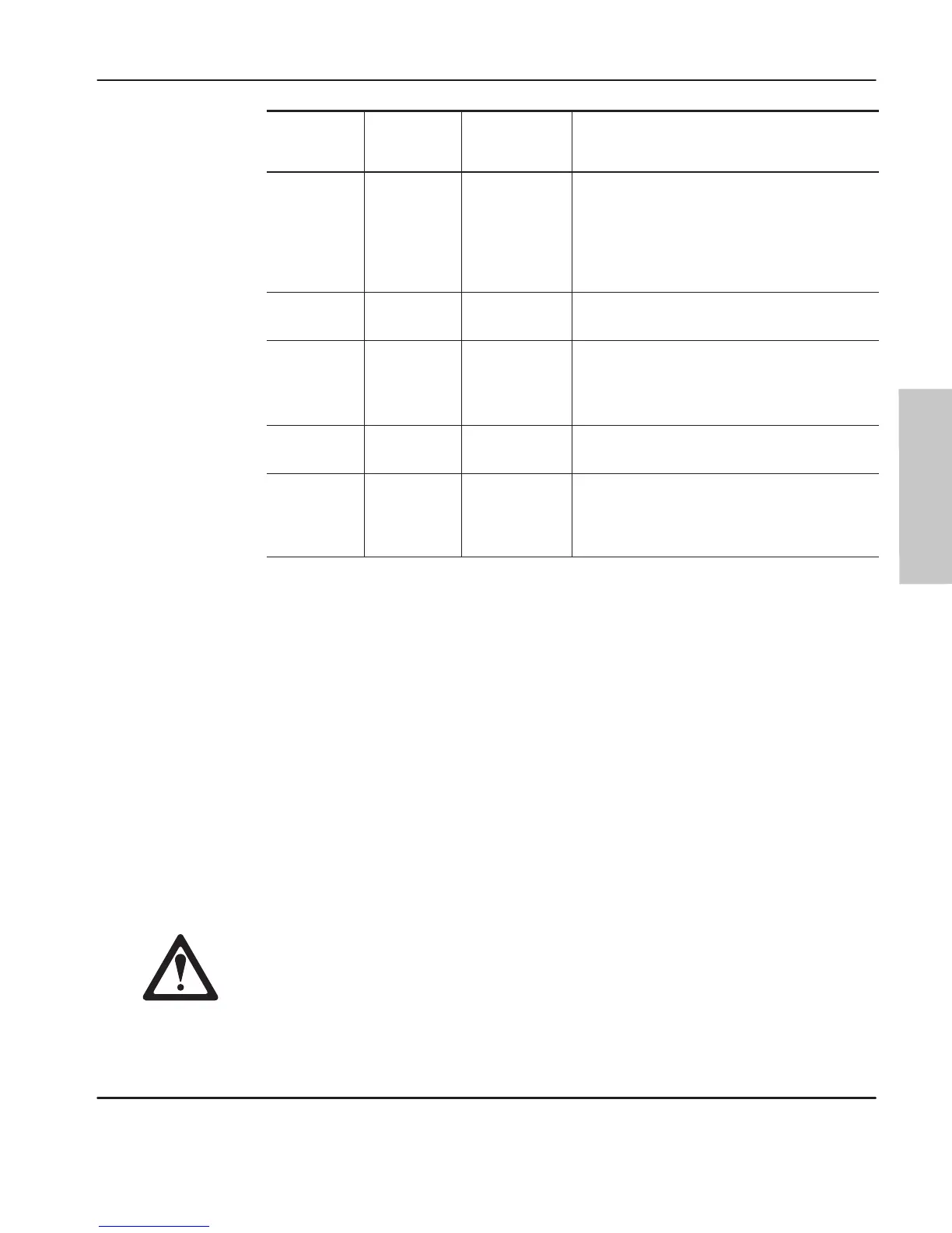
Parameter
Image
Location
Up Counter
Only
Bidirectional
Counters
Description
N7:5 Output Mask Output Mask
Identifies which group of four bits in the output
file (word 0) are controlled.
000F=bits 3–0
00F0=bits 7–4
0003=bits 0 and 1
00FF= bits 7–0
N7:6
Output
Source
Output High
Source
(Up count.) The status of bits in this word are
written “through” the mask to the actual outputs.
N7:7 High Preset High Preset
(Up count.) When the accumulator reaches this
value, the output source are written through the
output mask to the actual outputs, and the HSC
subroutine (file 4) will be scanned.
N7:8 Reserved
Output Low
Source
(Down count.) The status of bits in this word are
written “through” the mask to the actual outputs.
N7:9 Reserved Low Preset
(Down count.) When the accumulator reaches
this value, the output source are written through
the output mask to the actual outputs, and the
HSC subroutine (file 4) will be scanned.
The
bits in the output mask dir
ectly corr
espond to the physical outputs.
If a bit is set
to 1, the corresponding output can be changed by the high-speed counter. If a bit is
set to 0, the corresponding output cannot be changed by the high-speed counter.
The bits in the high and low sources also directly correspond to the physical outputs.
The high source is applied when the high preset is reached. The low source is
applied when the low preset is reached. The final output states are determined by
applying the output source over the mask and updating only the unmasked outputs
(those with a 1 in the mask bit pattern).
You can always change the state of the outputs via the user program or
programming device regardless of the output mask. The high-speed counter only
modifies selected outputs and output image bits based on source and mask bit
patterns when the presets are reached. The last device that changes the output image
(i.e., user program or high-speed counter) determines the actual output pattern.
Forces override any output control from either the high-speed counter or from
the output image. Forces may also be applied to the high-speed counter
inputs. Forced inputs ar
e r
ecognized by the high-speed counter (e.g., a forced
count input off and on increments the high-speed accumulator).
Programming
efesotomasyon.com - Allen Bradley,Rockwell,plc,servo,drive

 Loading...


