Using the Message Instruction
13–5
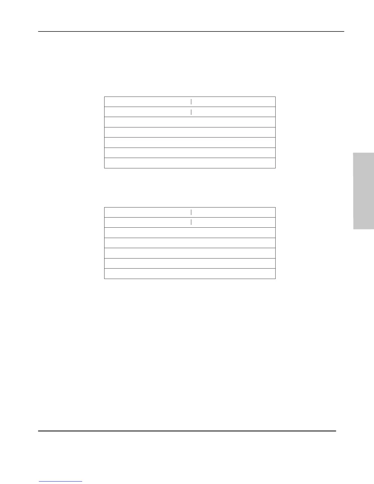
Control Block Layout
The
control block layouts shown below illustrate SLC500/ML1000 type messages.
EN ST DN ER EW NR TO Error Code
15 14 13 12 11 10 09 08 07 06 05 04 03 02 01 00
Reserved for length (in elements)
Control
Block Layout – SLC500/ML1000
Word
0
1
2
File Number
File Type (O, I, S, B, T, C, R, N)
Element Number
Subelement Number
3
4
5
6
Node Number
EN ST DN ER EW NR TO Error Code
15 14 13 12 11 10 09 08 07 06 05 04 03 02 01 00
Reserved for Length (in elements)
Control
Block Layout – 485CIF
Word
0
1
2
Offset Bytes
Not used
Not used
Not used
3
4
5
6
Node Number
Programming
efesotomasyon.com - Allen Bradley,Rockwell,plc,servo,drive

 Loading...


