Using the Message Instruction
13–19
END
2.0
]/[
N7:0
12
(EN)
(DN)
TON
TIMER ON DELAY
Timer T4:0
Time Base 0.01
Preset 600
Accum 0
(L)
N7:0
] [
N7:0
15
] [
T4:0
DN
2.1
2.2
2.5
2.6
2.4
8
(U)
N7:0
15
]/[
N7:0
13
]/[
N7:20
12
] [
N7:20
15
]/[
N7:20
13
(EN)
(DN)
TON
TIMER ON DELAY
Timer T4:1
Time Base 0.01
Preset 600
Accum 0
(L)
N7:20
] [
T4:1
DN
8
2.3
] [
N7:0
12
(EN)
(DN)
(ER)
MSG
READ/WRITE MESSAGE
Read/write READ
Target Device SLC500/ML1000
Control Block N7:20
Control Block Length 7
] [
N7:0
13
] [
N7:20
12
] [
N7:20
13
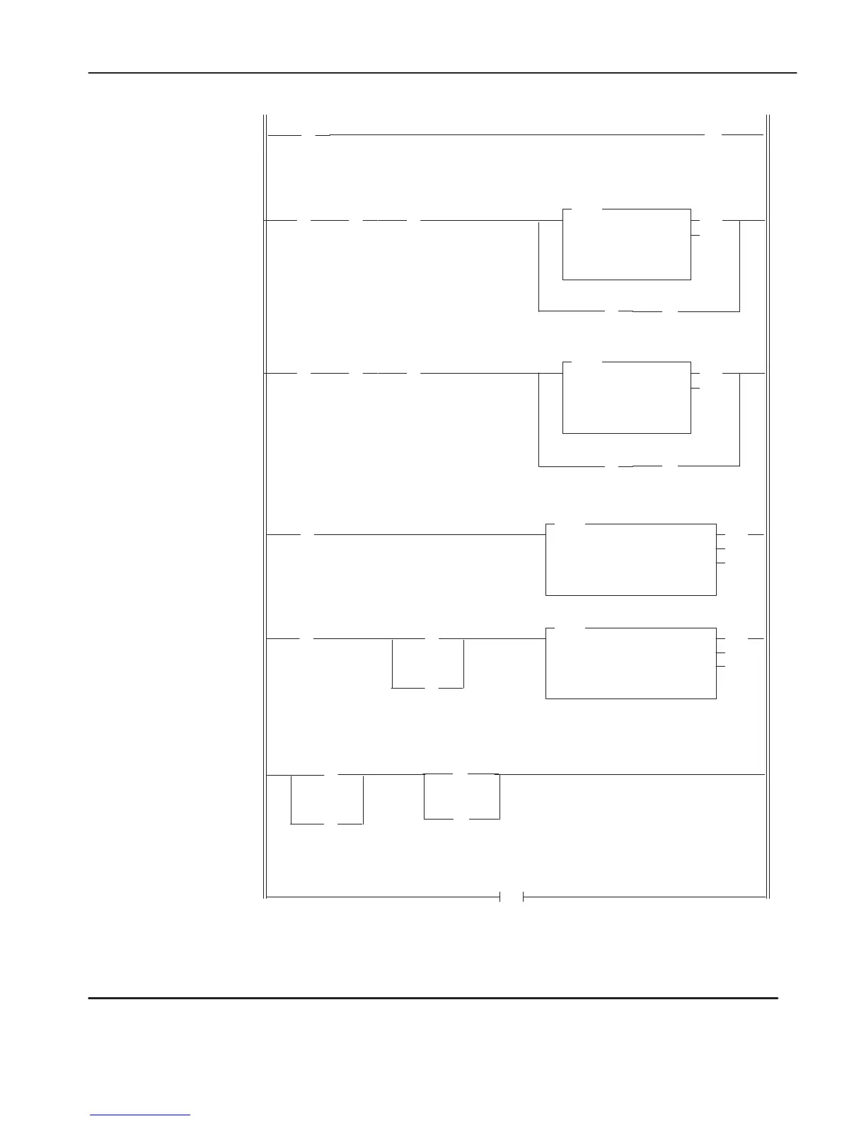
This
rung starts messaging each REM Run or RUN mode entry by clearing the EN bit of the first MSG instruction.
Same as above rung.
This rung sets the timeout value. (When using a SLC 5/03 or SLC 5/04 processor
, this rung and rung 2:2 are not
required because you can enter the value 6 into the T
imeout value field in the MSG instruction block.)
The MSG instruction energizes upon entry into the REM Run or RUN mode. No input conditions are required.
The MSG instruction is energized when the previous MSG instruction completes.
This rung resets all MSG instructions when the last MSG instruction has completed.
(EN)
(DN)
(ER)
MSG
READ/WRITE MESSAGE
Read/write WRITE
Target Device SLC500/ML1000
Control Block N7:0
Control Block Length 7
] [
S:1
15
] [
S:0
11
] [
S:0
11
(U)
N7:0
15
N7:20
(U)
15
efesotomasyon.com - Allen Bradley,Rockwell,plc,servo,drive

 Loading...


