Hardware
Installing
Y
our Controller
1–17
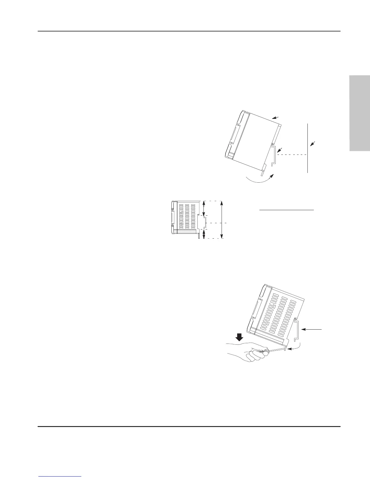
Using a DIN Rail
Use 35 mm (1.38 in.) DIN rails, such as item number 199-DR1 or 1492-DR5 from
Bulletin 1492.
To install your controller on the DIN rail:
1.Mount your
IN rail. (Make sure that the
placement of the controller on the DIN rail
meets the recommended spacing
requirements. Refer to controller
dimensions in appendix A.)
3.While pressing the controller against the
rail, snap the controller into position.
4.Leave the protective wrap attached until you
are finished wiring the controller.
2.Hook the top slot over the DIN rail.
20146
Side
iew
DIN
Rail
Protective Wrap
Mounting
Template
DIN
Rail
Call-out Dimension
A
84 mm (3.3 in.)
B
33 mm (1.3 in.)
C
16 mm (.63 in.)
A
B
C
To remove your controller from the DIN rail:
2.Holding the controller, pry downward on
the latch until the controller is released
from the DIN rail.
1.Pla
e a s
rewdriver in the
IN rail lat
h at
the bottom of the controller.
Side
iew
DIN
Rail
20147
efesotomasyon.com - Allen Bradley,Rockwell,plc,servo,drive

 Loading...


