Hardware
Wiring
Y
our Controller
2–5
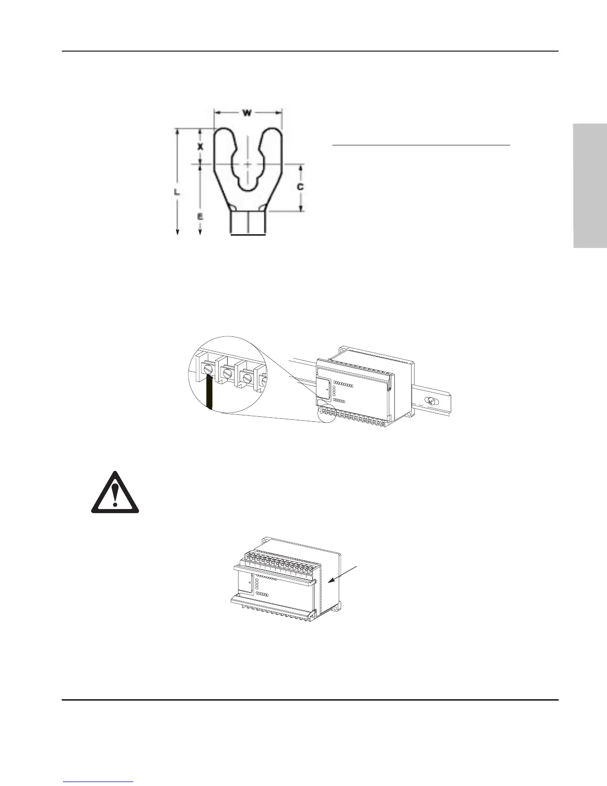
Note The
diameter of the terminal scr
ew heads is 5.5 mm (0.220 in.). The input and
output terminals of the micr
o contr
oller ar
e designed for the following spade lugs:
Call-out Dimension
C
6.35 mm (0.250 in.)
E
10.95 mm (0.431 in.) maximum
L
14.63 mm (0.576 in.) maximum
W
6.35 mm (0.250 in.)
X
3.56 mm (0.140 in.)
C+X
9.91 mm (0.390 in.) maximum
We
r
ecommend using either of the following AMP spade lugs: part number
53120-1, if using 22–16 AWG, or part number 53123-1, if using 16–14 AWG.
Note If
you use wir
es without lugs, make sur
e the wir
es ar
e secur
ely captur
ed by the
pressur
e plate. This is particularly important at the four end terminal positions
wher
e the pr
essur
e plate does not touch the outside wall.
20148i
Be car
eful when stripping wir
es. W
ire fragments that fall into the
controller could cause damage. Do not strip wires above a mounted
controller if the protective wrap is removed.
Protective
Wrap (remove after wiring)
efesotomasyon.com - Allen Bradley,Rockwell,plc,servo,drive

 Loading...


