EasyManuals Logo

Allen-Bradley MicroLogix 1000 User Manual

Allen-Bradley MicroLogix 1000
422 pages
To Next Page IconTo Next Page
To Previous Page IconTo Previous Page
Page #50 background imageLoading...
Page #50 background image
Hardware
Preface
MicroLogix 1000 Programmable Controllers User Manual
2–16
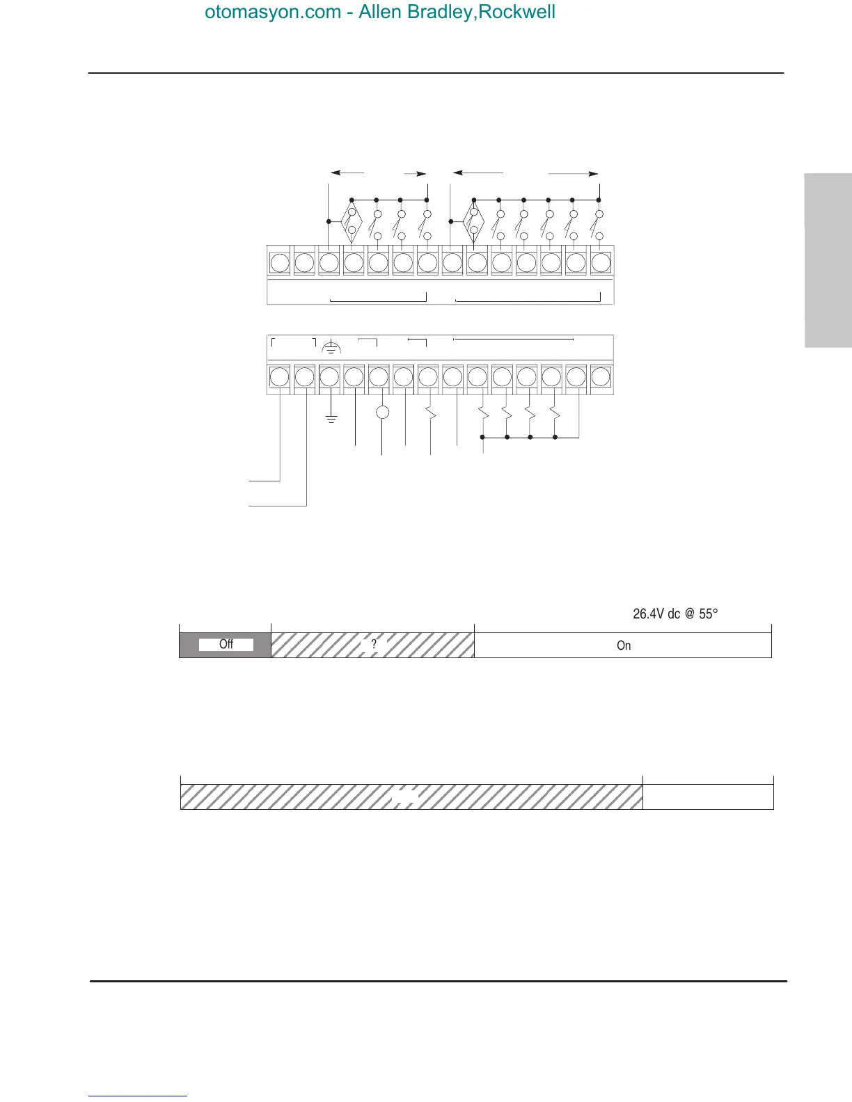
1761-L16BBB Wiring Diagrams (Sinking Input Configuration)
Note: Refer to page 2–4 for additional configuration options.
NOT
USED
NOT
USED
VAC
VDC
O/0
VAC
VDC
O/1
DC
24V+
O/2 O/3 O/4 O/5
I/9
I/0 I/1 I/2 I/3 I/4 I/5 I/6 I/7 I/8
DC
COM
DC
COM
DC
24V–
NOT
USED
VDC
Com
VDC +
14–30V dc
VDC
Com
VDC +
14–30V dc
CR
V
AC 1
V
AC 1
COM
V
AC 2
V
AC 2
COM
VDC 2
VDC 2
COM
VDC 1
VDC 1
COM
DC IN
+
24V –
Sourcing Outputs
1761-L16BBB Input Voltage Range
0V dc 5V dc 14V dc
ÉÉÉÉÉÉÉÉÉÉ
ÉÉÉÉÉÉÉÉÉÉ
On
?
Off
26.4V dc @ 55° C (131° F)
1761-L16BBB Output Voltage Range
0V dc 26.4V dc20.4V dc
Operating
Range
?
efesotomasyon.com - Allen Bradley,Rockwell,plc,servo,drive

Table of Contents

Questions and Answers:

Question and Answer IconNeed help?

Do you have a question about the Allen-Bradley MicroLogix 1000 and is the answer not in the manual?

Allen-Bradley MicroLogix 1000 Specifications

General IconGeneral
Communication PortsRS-232
Power Supply24V DC or 120/240V AC
Programming SoftwareRSLogix 500
ManufacturerAllen-Bradley
CategoryController
SeriesMicroLogix
Programming LanguageLadder Logic
Input Voltage24V DC or 120/240V AC
I/O Points10 to 32 points
Processor Type8-bit
Operating Temperature0…55 °C (32…131 °F)
Processor8-bit

Related product manuals