Preface
MicroLogix 1000 Programmable Controllers User Manual
2–20
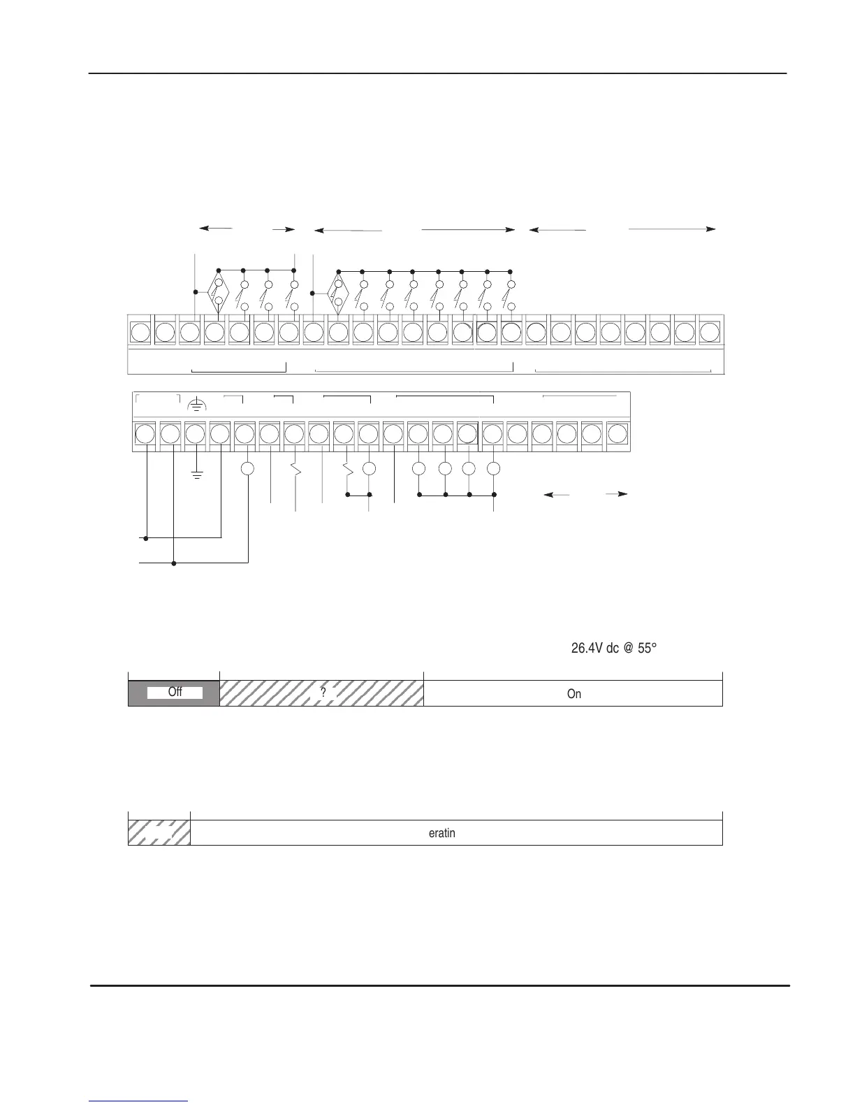
1761-L20BWB-5A Wiring Diagram (Sinking Input Configuration)
Note: Refer to page 2–4 for additional discrete configuration options.
Refer to pages 2–21 through 2–23 for additional information on analog
wiring.
NOT
USED
NOT
USED
VAC
VDC
O/0
VAC
VDC
O/1
VAC
VDC
O/2 O/3
VAC
VDC
O/4 O/5 O/6
NOT
USED
O/7
I/9 I/10
DC
COM
I/0 I/1 I/2 I/3 I/4 I/5 I/6 I/7 I/8 I/11
DC
COM
VDC
(–)
VDC +
14–30V dc
CR CR CRCR CR
V
AC 1
V
AC 1
COM
VDC 2
VDC 2
COM
VDC 3
VDC 3
COM
CR
VDC 1
VDC 1
COM
VDC (–)
VDC (+)
DC IN
+
24V –
IA
(–)
IA/3
I (+)
IA/2
I (+)
IA
SHD
IA/1
V (+)
IA
SHD
IA/0
V (+)
IA
(–)
14–30V dc
OA
(–)
OA/0
I (+)
OA/0
V (+)
OA
SHD
Analog
Channels
Analog
Channel
1761-L20BWB-5A Discrete Input Voltage Range
0V dc 5V dc 14V dc
On
?
Off
26.4V dc @ 55° C (131° F)
1761-L20BWB-5A Relay Output Voltage Range
0V dc 125V dc5V dc
0V ac 264V ac5V ac
?
Operating
Range
efesotomasyon.com - Allen Bradley,Rockwell,plc,servo,drive

 Loading...


