Preface
MicroLogix 1000 Programmable Controllers User Manual
4–12
You can also address at the bit level using mnemonics for timer, counter, or control
data types. The available mnemonics depend on the type of data. See chapters 6
through 13 for more information.
Specifying Indexed Addresses
The
indexed address symbol is the # character
. Place the # character immediately
before the file-type identifier in a logical address. Y
ou can use more than one
indexed address in your ladder program.
Enter the offset value in word 24 of the status file (S:24). All indexed instructions
use the same word S:24 to store the offset value. The processor starts operation at
the base address plus the of
fset. Y
ou can manipulate the offset value in your ladder
logic before each indexed address operation.
When you specify indexed addresses, follow these guidelines:
•
Make sure the index value (positive or negative) does not cause the indexed
address to exceed the file type boundary.
•
When an instruction uses more than two indexed addresses, the processor uses
the same index value for each indexed address.
• Set the index word to the offset value you want immediately before enabling an
instruction that uses an indexed address.
Instructions with a # sign in an address manipulate the offset value stored at
S:24. Make sure you monitor or load the offset value you want prior to using
an indexed addr
ess. Otherwise unpr
edictable machine operation could occur
with possible damage to equipment and/or injury to personnel.
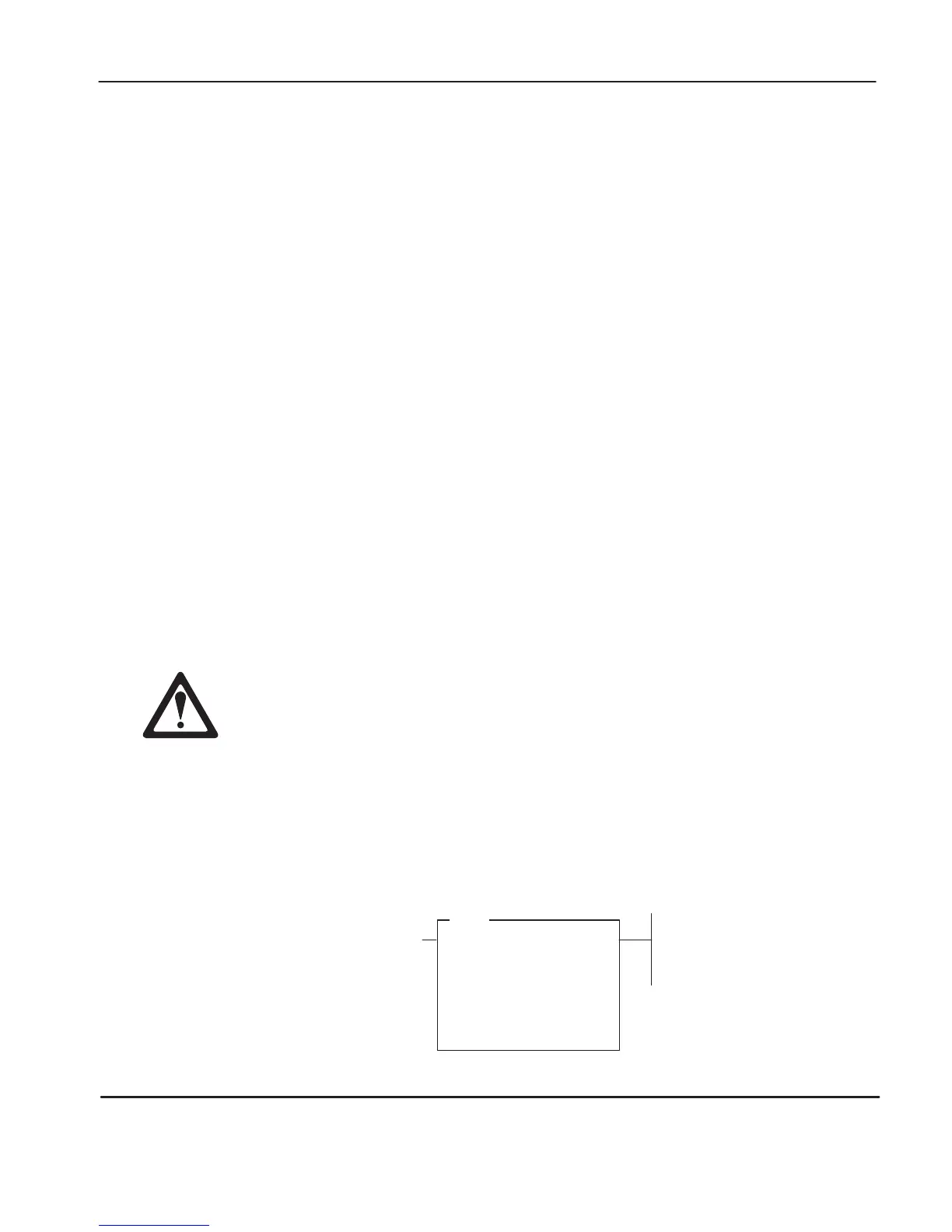
Example of Indexed Addressing
The
following Masked Move (MVM) example uses an indexed address in the
source and destination addresses. If the of
fset value is 10 (stored in S:24), the
processor manipulates the data stored at the base address plus the of
fset.
MVM
MASKED MOVE
Source #N7:10
0
Mask 0033
Dest #N7:50
0
efesotomasyon.com - Allen Bradley,Rockwell,plc,servo,drive

 Loading...


