PanelView Plus and PanelView Plus Compact 400 and 600 Terminals 9
Publication 2711P-IN002G-EN-P - November 2009
Communication modules for specific protocols can be ordered as separate components for
field installation or factory assembled to base unit (with communication interface) per your
configuration.
Parts List
The terminals are shipped with these items:
• Power terminal block, AC or DC
• Mounting clips
• Installation instructions and panel cutout
Required Tools
These tools are required for installation:
• Panel cutout tools
• Small, slotted screwdriver for securing power and RS-232 port connections
IMPORTANT
When using the DH-485 module, catalog number 2711P-RN3, with PanelView Plus 400
and 600 terminals, the cable length must not exceed 30 m (98 ft) to comply with CE
requirements. For longer cable lengths, use the 1761-NET-AIC or 1747-AIC module.
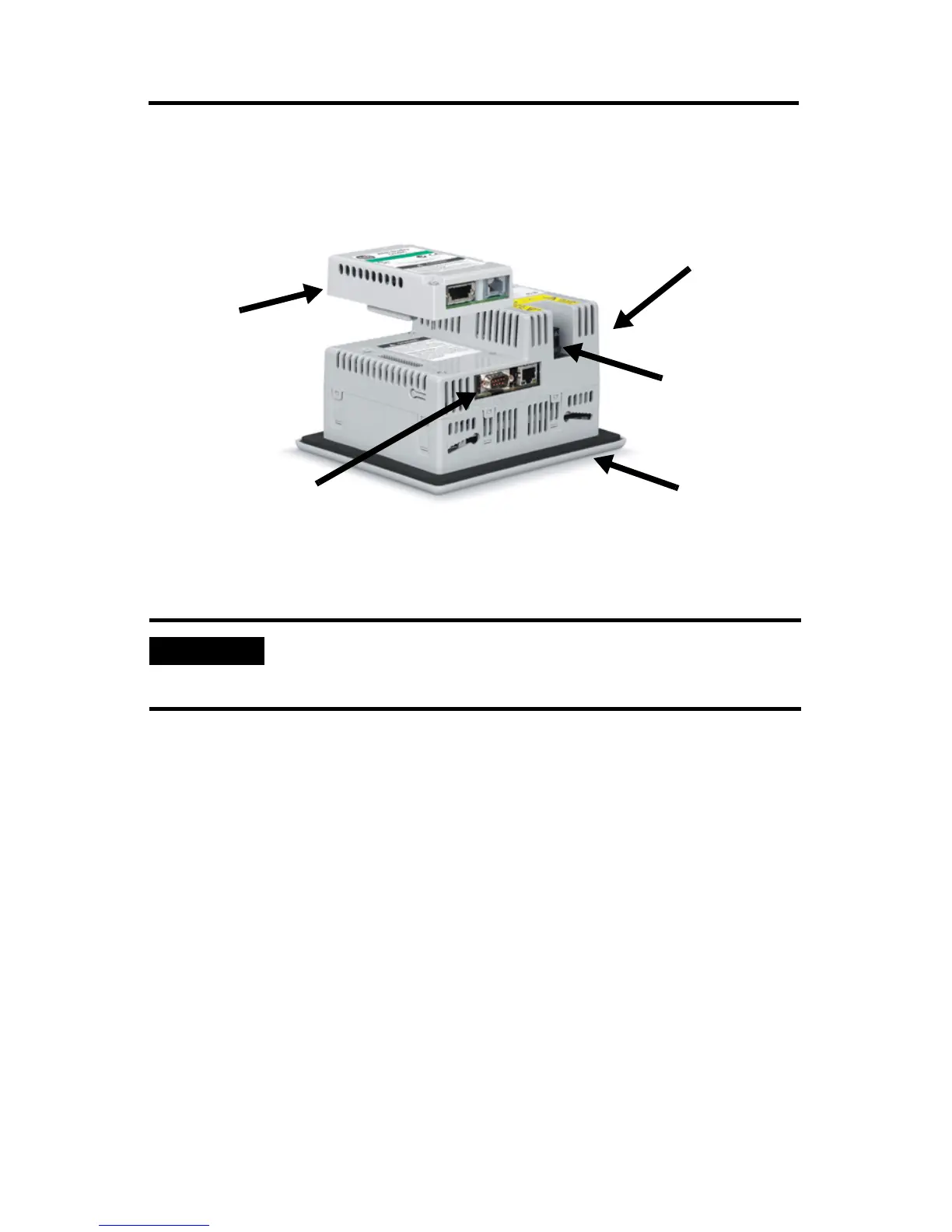
Power Connection,
AC or DC
Communication
Module
Base Configured Unit with:
• USB and RS-232 Ports Only
• USB, RS-232, and Ethernet Ports or
• USB, RS-232, and Ethernet Ports with Interface for Communication Module.
Display
Compact Flash
Card Slot (not shown)
AB Parts
 Loading...